
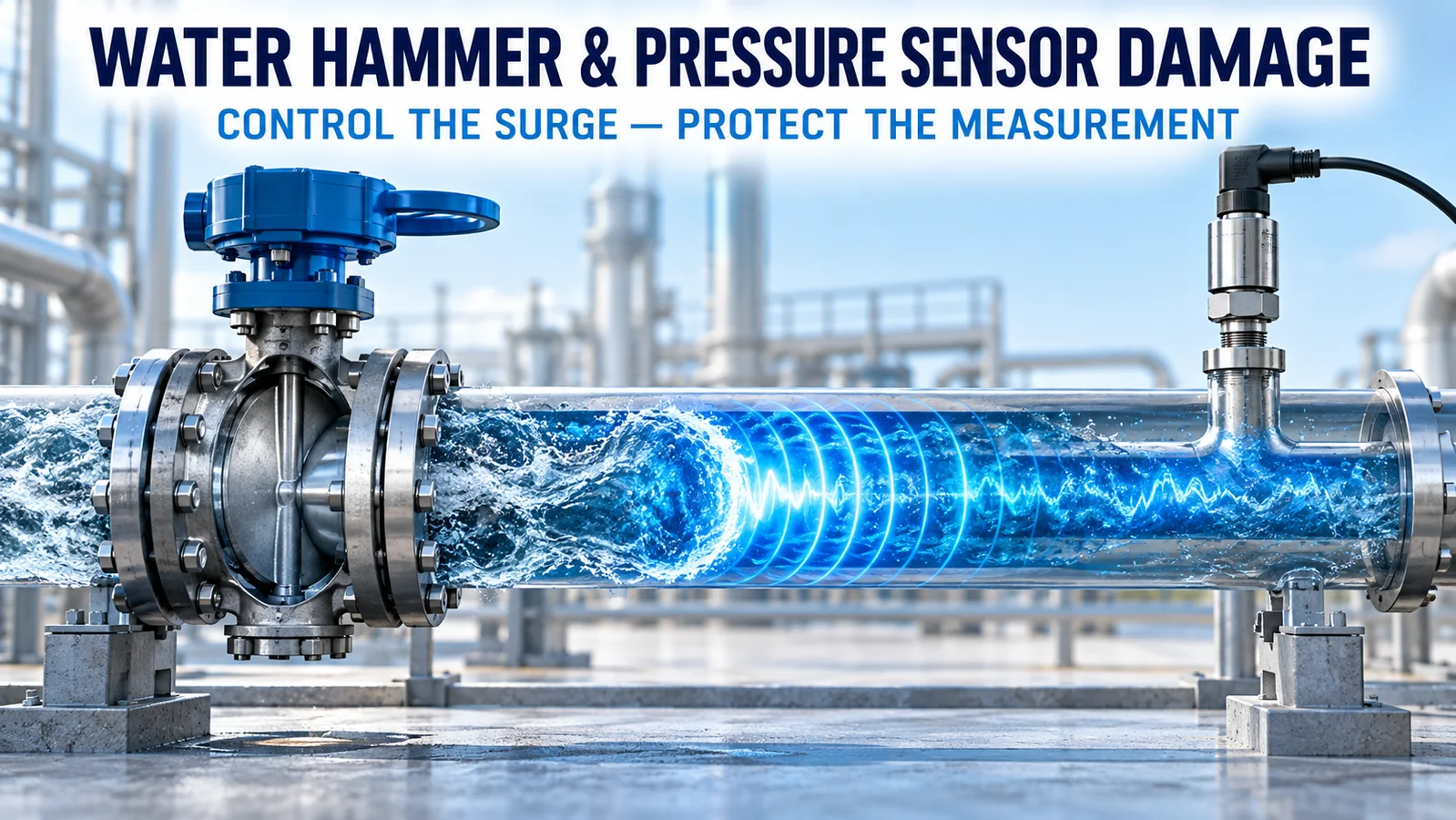
A water hammer pressure sensor problem begins when flow velocity changes so quickly that the liquid’s momentum becomes a travelling pressure wave. The peak can be much higher than the normal line pressure and much shorter than the update rate of a PLC trend or mechanical gauge. Repeated events can shift calibration, deform a diaphragm, damage seals or fatigue the pressure boundary.
Protection should follow a hierarchy: reduce the hydraulic transient at its source, add an engineered surge-control device where required, select a sensor with verified dynamic pressure capability, and use local damping only when its response-time tradeoff is acceptable.
What Is Water Hammer?
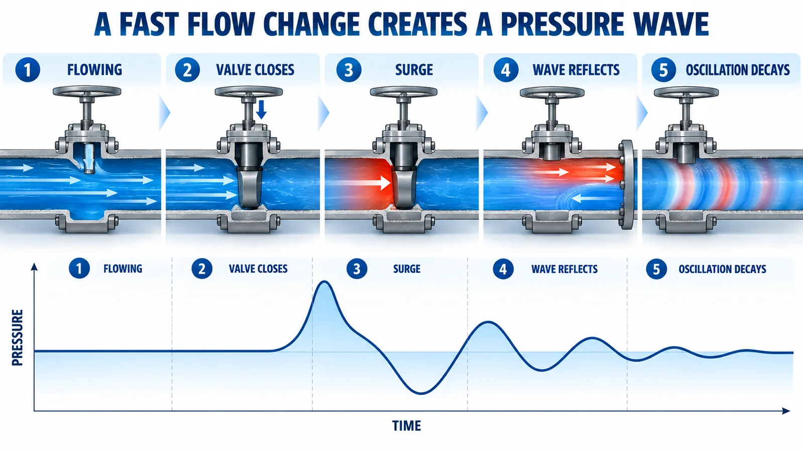
Water hammer is the transient pressure change produced when liquid velocity changes rapidly in a closed piping system. Fast valve closure, pump start or stop, check-valve slam, power loss, sudden demand changes and rapid filling of empty pipe can all initiate it.
Der Grundfos explanation of water hammer describes the event as a sudden pressure buildup caused by a rapid change in water momentum. The pulse travels through the pipe, reflects at boundaries and may oscillate before friction dissipates its energy.
A simplified Joukowsky relationship is:
ΔP = ρ × a × ΔV
Wo ρ is fluid density, a is wave speed and ΔV is the rapid velocity change. This equation is useful for understanding sensitivity, not for replacing a full transient analysis. Pipe elasticity, supports, air pockets, valve characteristics, branch geometry and pump behavior influence the real waveform.
Why Can Normal Pressure Look Safe?
A system may operate steadily at 5 bar while experiencing millisecond peaks far above that value. A mechanical gauge has inertia, a PLC may sample slowly, and software filtering may suppress the spike. The stored trend then shows only a small bump or no event at all.
This creates a common failure pattern: the selected range comfortably covers normal pressure, yet sensors drift or fail without an obvious overpressure record. Selection based only on the steady-state maximum misses peak amplitude, duration, repetition and negative-pressure phases.
Record the operating event that causes the noise: valve closure, pump trip, check-valve movement or rapid demand change. The sound itself is evidence of a transient but not a measurement of its magnitude.
How Does Water Hammer Damage a Pressure Sensor?
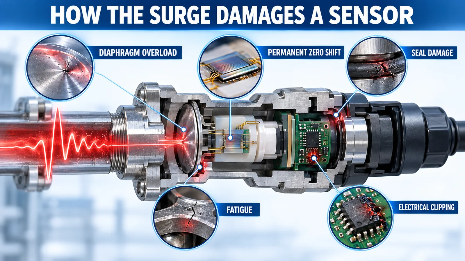
Diaphragm overload
A high positive peak can drive the sensing diaphragm beyond its intended elastic range. The result may be a permanent zero shift, span change, nonlinearity or rupture.
Repeated fatigue
Even if one event does not cause immediate failure, thousands of rapid cycles can fatigue a thin diaphragm, weld or process connection. Dynamic life depends on amplitude, waveform and construction.
Seal and joint damage
Pressure reversals and local deformation can disturb O-rings, gaskets, adhesive bonds or threaded seals. Leakage may appear later than the original event.
Negative pressure and cavitation
Reflected waves can create pressure below normal operating conditions. Vapor cavities may form and collapse, adding local impact. Verify whether the sensor tolerates vacuum or reverse pressure.
Electrical clipping
The sensing element may survive while the electronics saturate at their output limit. A clipped 20 mA, maximum-voltage or maximum-digital-code trace hides the true pressure peak.
Measure the Transient Before Choosing Protection
Use a sensor, acquisition channel and sampling rate fast enough for the expected event. Mount the diagnostic sensor where the damaging pressure is suspected, not only at a convenient remote header.
The measurement chain should have:
- adequate pressure range and documented overload capability;
- response time faster than the event features of interest;
- sampling rate and anti-alias filtering suitable for the bandwidth;
- synchronized valve, pump or controller status signals;
- a rigid, short pressure connection with known dynamic behavior;
- a reference or calibration check before and after testing.
Record several worst credible operations. One gentle commissioning cycle does not represent emergency shutdown, power loss or a nearly empty pipe.
Sampling must be designed around duration, not only peak pressure. A high-speed local recorder can reveal an initial spike followed by reflections, while a slow historian stores only a moving average. Capture raw data at the diagnostic rate and then create a lower-rate operational trend. Confirm that the sensor output and input channel do not saturate; once either clips, the trace gives only a lower bound for the true peak.
Compare measurements at more than one location when the network is complex. The highest surge may occur at a closed valve, elevated branch or remote dead end rather than next to the pump.
Protect the Hydraulic System First
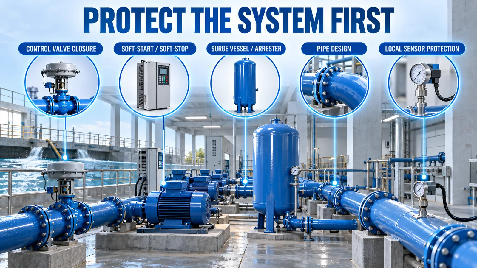
The strongest mitigation usually changes the event that creates the wave:
- slow valve closing within process constraints;
- use controlled pump acceleration and deceleration;
- prevent check-valve slam with correctly selected hardware;
- use a pipe-filling sequence that avoids rapid pressurization of empty lines;
- review pipe diameter, velocity, support and branch geometry;
- install an engineered surge vessel, accumulator or arrester where analysis requires it;
- maintain air-management devices and expansion volume.
Der Grundfos soft pressure build-up guidance illustrates a two-phase filling and pressure-building approach intended to reduce water hammer in relevant water systems.
System mitigation protects valves, fittings, pumps and pipes—not just the measurement point. It should therefore be reviewed by the hydraulic-system designer.
Air pockets deserve specific investigation. Entrained or trapped air changes local compressibility and can alter wave behavior, cause column separation or create violent collapse when water rejoins. High points, partially filled lines and rapid filling procedures should be reviewed together. Air-release and vacuum devices must be selected and maintained for the actual hydraulic duty; adding an unapproved vent can create another failure mode.
Local Pressure Sensor Protection Methods
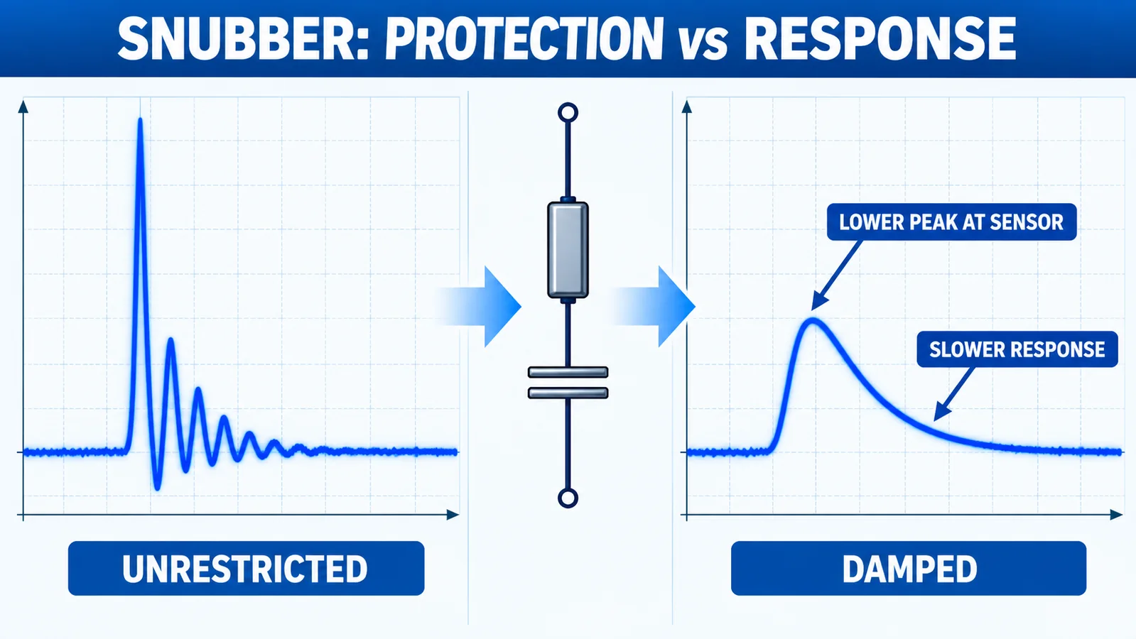
Snubber or restrictor
A calibrated small passage slows pressure transfer to the sensor cavity. It can reduce the sensor-side peak but also slows response and can clog. Select it for the medium, viscosity, contamination and required bandwidth.
Pulsation damper
A purpose-designed damper can reduce cyclic pump ripple or pulsation. It must be compatible with process pressure, temperature and fluid.
Remote mounting and impulse line
Moving the transmitter away from vibration or heat can help, while the line adds hydraulic damping. However, trapped gas, long tubing, elevation and temperature can introduce delay and error.
Diaphragm seal or isolation device
An engineered isolation arrangement may protect against media or clogging, but its fill system changes dynamic response and temperature behavior. It is not automatically a water-hammer solution.
Surge-rated transmitter
Choose a sensor whose exact range has documented overload/proof behavior appropriate to the measured transient. Do not assume the highest catalog range or stainless construction alone provides sufficient surge life.
How Much Range and Overload Margin Is Needed?
Start with measured or analytically justified transient pressure, not a universal multiplier. Separate:
- normal operating range;
- control and alarm range;
- recurring transient peak;
- occasional upset or test pressure;
- negative pressure;
- proof/overload limit;
- burst/containment limit.
A higher range increases headroom but increases pressure error in applications where accuracy is stated as %FS. The pressure sensor accuracy FS versus reading guide explains this tradeoff. The selected range must preserve useful normal-pressure resolution while surviving the verified dynamic environment.
Proof, overload and burst terms are not interchangeable. Use the manufacturer’s definition and the exact range table.
Where Should the Sensor Be Installed?
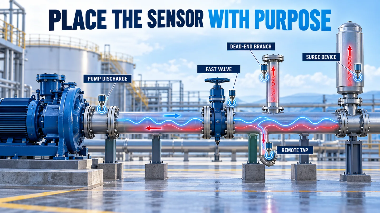
Placement determines what the sensor experiences. Pump discharge, fast-closing valves, dead-end branches and high points can show different waveforms. A remote pressure tap may report the control pressure correctly while missing the local peak at a vulnerable valve.
Avoid unsupported heavy transmitters on small vibrating branches. Use approved fittings and seal methods, keep liquid lines free of trapped gas when dynamic response matters, and orient drains or bleed points deliberately. The NPT- oder G-Gewindeführung helps prevent a connection mismatch from becoming a mechanical weakness.
For constant-pressure booster control, coordinate transient protection with the control location described in the booster pump pressure sensor guide. Damping must not make the feedback signal so slow that the controller becomes unstable.
How Do WPCK68 and WPCK07 Fit?
Der Winsen WPCK68 is a compact diffused-silicon transmitter. Its current page lists 0.2–2.3 V and I²C outputs, a range family up to 60 MPa, response time at or below 1 ms and range-dependent overload values. Confirm the exact range chart and electrical interface for the ordered unit.
Der Winsen WPCK07 is an industrial transmitter family with multiple outputs including 4–20 mA and a broad range family. Its current page also lists fast response. A fast sensor may reveal a transient that a slow display hides, but fast response does not itself guarantee survival.
Der WPCK07 manual and the exact range table should be reviewed before assigning overload margin. Page-level family specifications cannot replace a configuration-specific surge review.
Neither model name is a blanket water-hammer rating. Submit normal pressure, measured peak, negative pressure, waveform duration, event frequency, medium, temperature, connection and desired output for review.
Verify the Protection

- Record the baseline transient with adequate bandwidth.
- Identify the initiating event and pressure-wave locations.
- Implement the hydraulic or local protection.
- Repeat the same worst credible operation.
- Compare peak, negative phase, oscillation duration and repetition.
- Recheck sensor zero and span after cycling.
- Inspect fittings, seals and supports for leakage or movement.
- Trend operating events to detect degradation.
If a snubber makes the trend smooth, verify that the actual pipe surge also decreased or that the sensor-side attenuation is sufficient by design. A smooth PLC trace alone does not prove the system is protected.
FAQ
Can I fix water hammer by installing a higher-range sensor?
It may increase sensor survival margin, but it does not protect the piping system and may reduce normal-pressure accuracy. Address the hydraulic transient first.
Does a snubber always protect the sensor?
No. Performance depends on the restriction, cavity, fluid, contamination and waveform. It can also clog or slow control response.
Why did the sensor fail when the PLC never exceeded full scale?
The transient may have been faster than the scan rate or clipped by the sensor output, input range or filter.
Is water hammer only a high-pressure problem?
No. Low-pressure systems can still experience damaging pressure changes, vacuum phases, cavitation and repeated fatigue.
Abschluss
A water hammer pressure sensor should be selected from the measured dynamic environment, not only the normal gauge reading. Reduce rapid flow changes, engineer surge control, verify range-dependent overload capability and treat local damping as a response-time tradeoff. For product review, Wenden Sie sich an Winsen with the pressure trace and complete operating conditions.
