
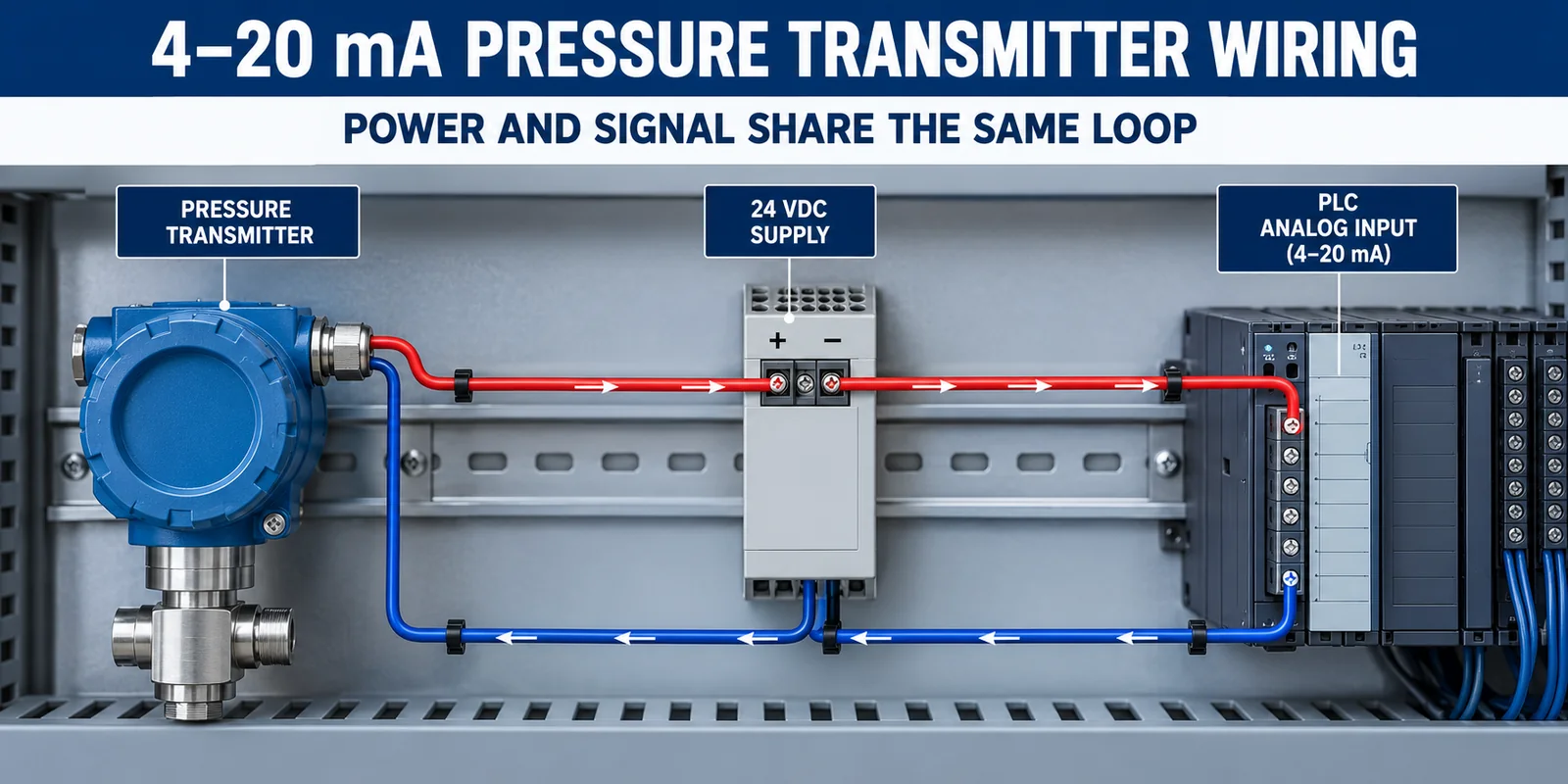
Correct 4-20mA pressure transmitter wiring uses one continuous series circuit. In a two-wire transmitter, the same pair of conductors powers the electronics and carries the measurement signal. The transmitter regulates loop current: 4 mA represents the configured lower-range value and 20 mA represents the upper-range value.
The most common mistakes are wiring the transmitter across a voltage input, adding a second supply to an active PLC input, forgetting loop voltage drops or assuming wire colors without checking the exact manual.
How Does a Two-Wire 4–20 mA Loop Work?
A basic loop contains:
- a DC power source;
- a two-wire pressure transmitter;
- a current-measuring PLC, DCS or DAQ input;
- the cable and any barriers or isolators.
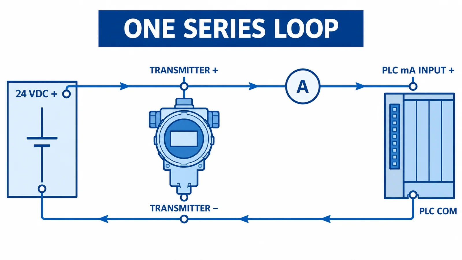
These components are connected in series. Current leaves the positive supply, passes through the transmitter and receiver, and returns to the supply. Depending on the input design, the receiver may appear before or after the transmitter in the series path, but there must be only one closed current path.
Der NI current-loop fundamentals explains the same core behavior: 4 mA is the live zero, 20 mA is full scale, and a precision shunt can convert loop current to a measured voltage.
Live zero is useful because zero process pressure can still produce 4 mA. A current near 0 mA can therefore indicate an open wire, loss of power or failed transmitter rather than a valid lower-range reading. Exact fault-current behavior must come from the transmitter and control-system specifications.
Active vs Passive PLC Current Input
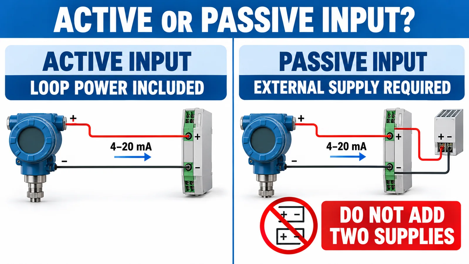
Before connecting anything, determine whether the analog input is active or passive.
Active current input
An active input provides loop power or excitation at its terminals. The transmitter is connected directly according to the module diagram. Adding an external supply without an approved wiring arrangement can place two sources in conflict.
Passive current input
A passive input measures current but does not power the loop. It requires an external DC supply in series. Many PLC modules offer configurable active/passive channels or different terminal groups, so read the exact module manual.
Do not decide from the labels “AI+” and “AI−” alone. Check whether the channel expects a current source, current sink, externally powered transmitter or loop-powered transmitter.
The words “sourcing” and “sinking” are used inconsistently across vendors. One manual may describe what the module supplies, while another describes the direction of conventional current at the terminal. Resolve the ambiguity with the manufacturer’s connection diagram and terminal function table. A continuity sketch made before wiring is often faster than troubleshooting a powered cabinet.
Basic Two-Wire Wiring Sequence
For a common externally powered passive-input loop, the conceptual sequence is:
Supply + → Transmitter + → Transmitter − → PLC mA input + → PLC COM → Supply −
The actual terminal order may differ, and some input modules internally connect COM to supply negative. Follow the drawings for both the transmitter and receiver.
Safe working steps are:
- Confirm the ordered transmitter output is 4–20 mA.
- Confirm the permitted supply range and polarity.
- Identify active or passive receiver behavior.
- De-energize the circuit.
- Connect the loop as a series path.
- Check for unintended ground connections.
- Energize with current limiting where appropriate.
- Measure loop current and compare it with applied pressure.
Never put an ammeter directly across a power supply. To measure loop current, open the loop and insert the meter in series, or use an approved loop calibrator/test point.
How Does a 250-Ohm Shunt Produce 1–5 V?
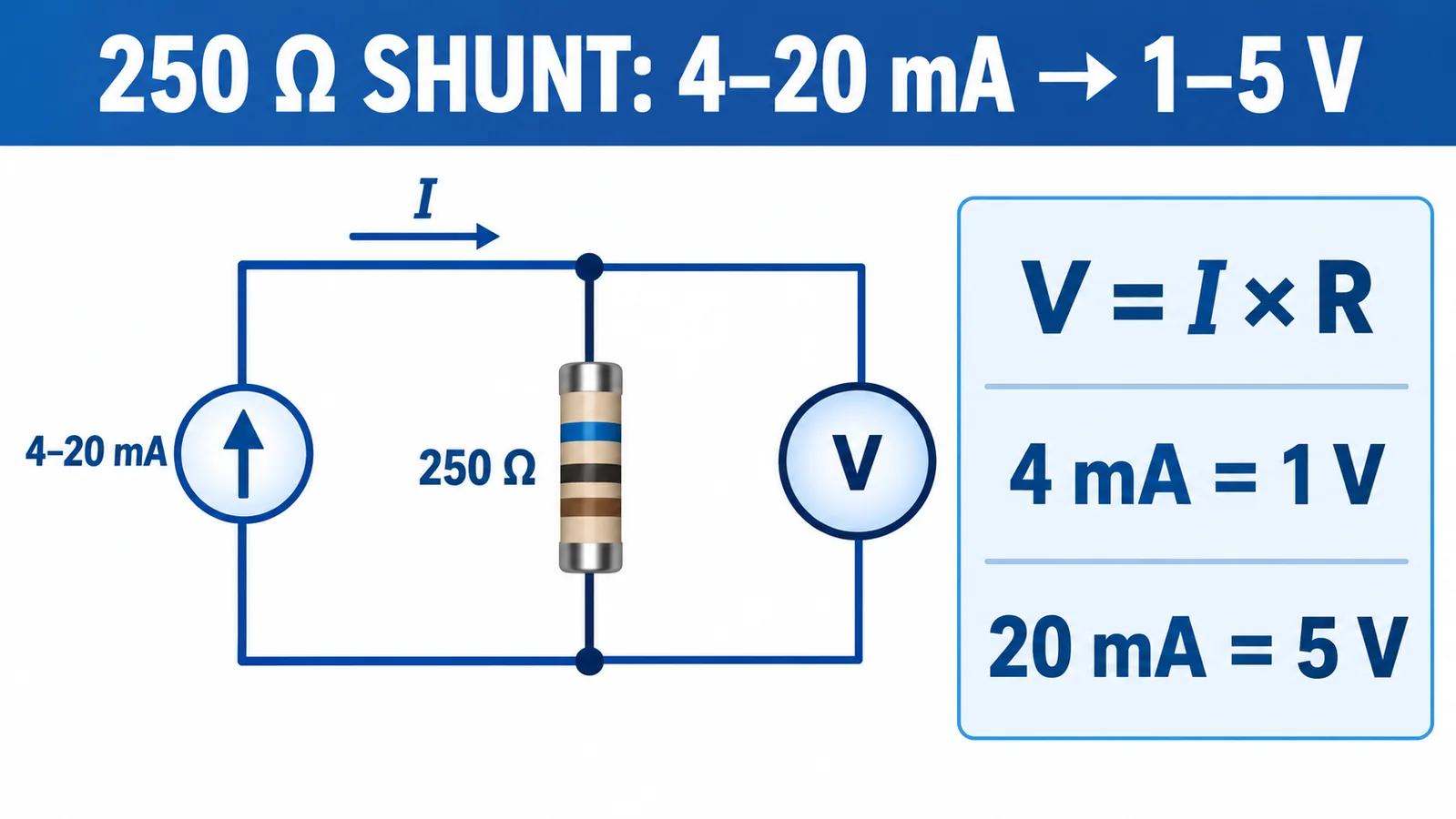
Ohm’s law gives:
V = I × R
With a 250 Ω resistor:
- 4 mA × 250 Ω = 1 V;
- 12 mA × 250 Ω = 3 V;
- 20 mA × 250 Ω = 5 V.
This is useful when a receiving device measures 1–5 V rather than current. Use a resistor with suitable tolerance, temperature coefficient, power rating and voltage rating. At 20 mA, dissipation is I²R = 0.1 W, so the design should include reasonable power margin.
Do not add an external shunt if the PLC current input already contains one. The extra resistance changes the loop load and can cause insufficient compliance voltage.
Calculate the Loop Voltage Budget
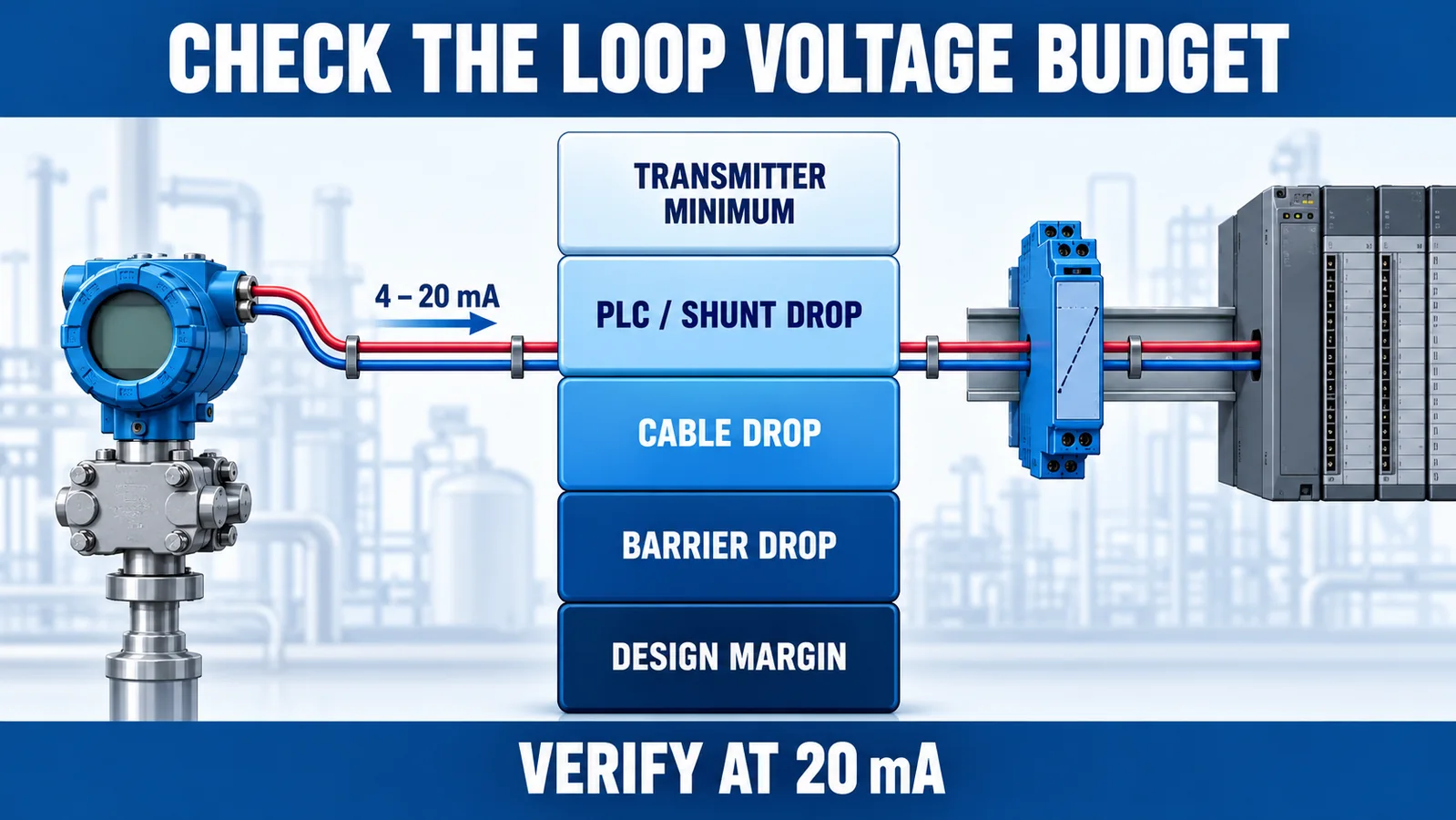
The supply must cover every voltage drop at the maximum current. A useful check is:
V_supply ≥ V_transmitter_min + I_max × (R_input + R_wire + R_other) + V_barriers + margin
Assume a transmitter needs at least 10 V, the receiver is 250 Ω, total loop wire is 80 Ω and there are no barriers. At 20 mA:
- receiver drop = 0.020 × 250 = 5.0 V;
- wire drop = 0.020 × 80 = 1.6 V;
- minimum before margin = 10 + 5 + 1.6 = 16.6 V.
A regulated 24 V supply leaves 7.4 V for design margin and any additional series devices. If an intrinsic-safety barrier or isolator adds a specified drop, subtract it from the available budget.
Check the worst-case supply minimum, highest loop current, maximum cable resistance at temperature and maximum receiver resistance. A loop can appear correct at 4 mA but saturate below 20 mA when voltage headroom runs out.
PLC Scaling From Current to Pressure
For a transmitter configured 0–10 bar:
Pressure = (Current − 4 mA) / 16 mA × 10 bar
Therefore 4 mA equals 0 bar, 12 mA equals 5 bar and 20 mA equals 10 bar. For a nonzero lower range, use:
PV = LRV + (Current − 4) / 16 × (URV − LRV)
Store the lower-range value, upper-range value and engineering unit with the channel configuration. Confirm whether the PLC raw count is already scaled and how it represents underrange, overrange and faults.
Der pressure units guide helps prevent a correctly wired loop from being displayed in the wrong unit or pressure reference.
Shielding, Grounding and Isolation
Use the cable type recommended by the transmitter and control-system manufacturers. Twisted conductors help reject magnetic interference. A shield can reduce electric-field coupling, but it should be terminated according to the site grounding design—often at one controlled point—to avoid unintended shield current.
Ground loops occur when connected equipment uses different ground potentials. Symptoms can include offset, noise, unstable readings or excessive current. Isolation may be needed between field wiring and the control system, especially across buildings, long routes or separately grounded equipment.
Keep signal cable separated from motor, VFD and contactor wiring where practical. Cross power conductors at right angles rather than running alongside them for long distances. Bond enclosures and surge protection according to electrical and hazardous-area requirements.
For intrinsically safe or hazardous-area loops, use only approved barriers, grounding arrangements, cable parameters and installation practices. The barrier adds series voltage drop and may restrict capacitance or inductance. Verify entity parameters and available transmitter voltage with the responsible safety engineer; a generic two-wire diagram does not establish hazardous-area compliance.
Surge protection also needs coordination. A protector that clamps too low or adds excessive leakage can disturb the loop, while an ungrounded protector may provide little benefit. Include it in the voltage budget and functional test.
Common 4–20 mA Wiring Faults
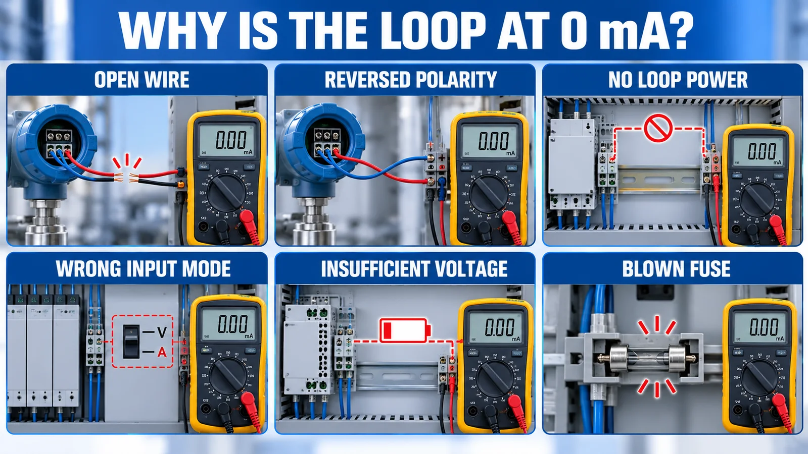
Loop reads 0 mA
Check supply voltage, fuse, circuit continuity, polarity, disconnected terminals and whether the input is configured for current. Measure voltage directly at the transmitter terminals while the loop is connected.
Loop is stuck near 4 mA
Verify applied pressure, configured lower and upper ranges, impulse line blockage and whether the transmitter has sufficient pressure reference. Confirm the PLC is reading the correct channel.
Loop cannot reach 20 mA
Calculate the voltage budget. Excessive receiver resistance, long cable, barriers or a low supply can remove compliance headroom. Also verify applied pressure with a reference.
Das Lesen ist laut
Inspect grounding, shielding, cable routing, power-supply ripple, VFD coupling and process pulsation. Do not hide a mechanical pressure problem with heavy software averaging.
PLC shows an inverted value
Check scaling and polarity. A correctly wired two-wire transmitter should still follow the manufacturer’s defined current direction; swapping leads commonly opens or disables the loop rather than creating a valid reversed scale.
Der pressure sensor installation guide covers mechanical and electrical mistakes outside the loop itself.
How Do WPCK07 and WPCK63 Fit?
Die jetzige Winsen WPCK07 page lists 4–20 mA among its output options and states 24 V working conditions for 4–20 mA or RS485 versions. The exact ordered output, connector, terminals, supply limits and hazardous-area conditions must be confirmed from the current manual and order code before wiring.
Use the WPCK07 manual for the delivered unit’s wiring and specification details. If the nameplate, order code and manual disagree, stop and obtain clarification rather than testing alternate terminal combinations under power.
Die jetzige Winsen WPCK63 page lists 0.2–2.3 V or I²C as its standard page outputs, with other outputs customizable. It should not be treated as a standard two-wire 4–20 mA device unless the specific supplied configuration and wiring document explicitly say so.
This distinction is important: product-family appearance does not identify the electrical interface. Verify the nameplate and documentation for the exact unit in hand.
Commissioning Checklist
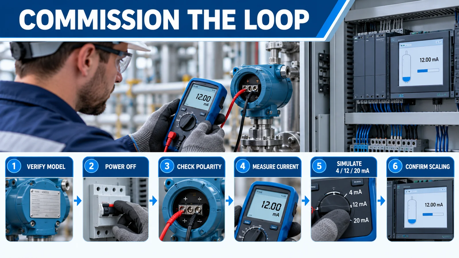
- Confirm model, output, range and pressure reference.
- Confirm active/passive input and supply ownership.
- Check polarity and series continuity with power off.
- Verify insulation and shield termination.
- Measure transmitter terminal voltage at 4 and 20 mA conditions.
- Use a loop calibrator or pressure reference to check 4, 12 and 20 mA.
- Confirm PLC raw counts, engineering units and range scaling.
- Test alarm, underrange, overrange and open-circuit behavior.
- Record wiring drawing, cable, barrier and channel configuration.
- Close covers and verify ingress protection after testing.
FAQ
Does a two-wire transmitter need a separate signal wire?
No. The same two conductors carry power and the regulated current signal.
Can I connect a 4–20 mA transmitter to a 0–10 V input?
Not directly. An approved shunt resistor or signal conditioner can convert current to voltage if the input, grounding and voltage budget support it.
Why do I measure 24 V with the loop disconnected?
With an open loop, little or no current flows, so the supply may appear almost entirely across the open terminals. Diagnose the energized closed loop using safe procedures.
Is 4 mA always zero pressure?
It represents the configured lower-range value, which could be zero, vacuum or another pressure.
Abschluss
Reliable 4-20mA pressure transmitter wiring starts by identifying the output and input types, then building one series loop with enough voltage headroom. Confirm polarity from the exact manual, calculate every voltage drop, test PLC scaling and document the result. For configuration support, Wenden Sie sich an Winsen with the model, output code, supply, receiver resistance and cable length.
