
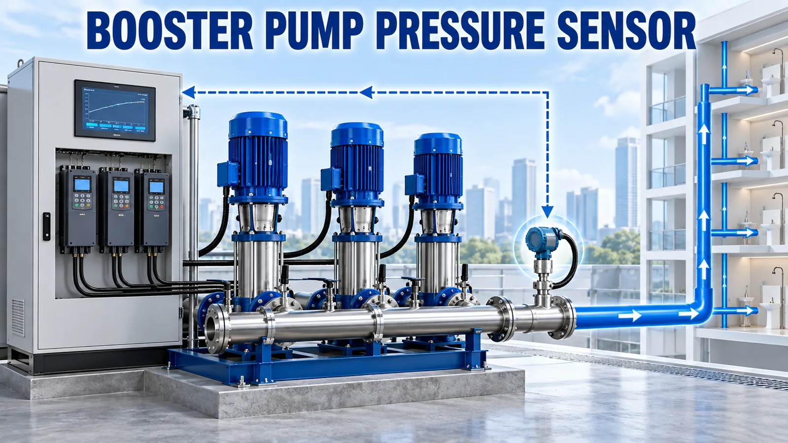
A booster pump pressure sensor is the feedback element that tells a controller whether the water-supply pressure is below, at or above its setpoint. In a variable-speed system, the controller compares this measured pressure with the target, changes pump speed or stages pumps, and repeats the calculation continuously.
The best sensor is therefore not simply the model with the smallest accuracy number. It must measure the right point, survive the hydraulic transients, provide an output the controller can use, and respond predictably enough for stable closed-loop control.
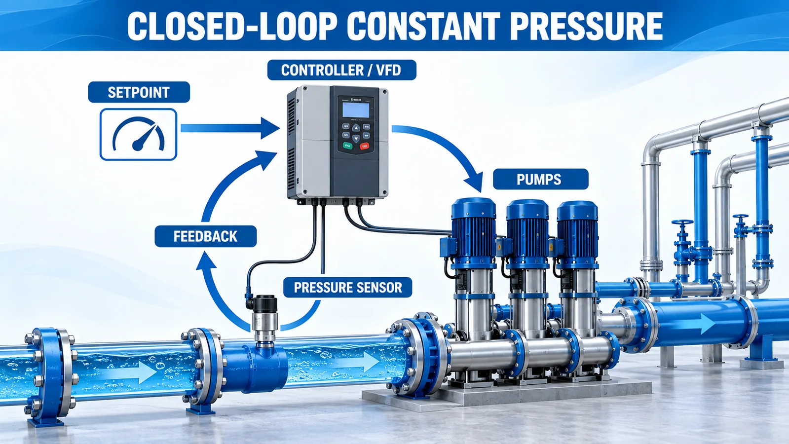
What Is the Short Selection Answer?
For most building or industrial booster systems, start with a gauge-pressure transmitter installed on the discharge manifold or at the pressure point the controller is intended to regulate. Select a normal operating range that uses a meaningful part of the span, then confirm that the device’s safe overload and surge strategy cover pump starts, valve closures and water hammer.
Choose the electrical output from the controller backward. A 4–20 mA loop is commonly practical for longer plant cables and PLC inputs. A conditioned voltage output can suit short OEM wiring. I²C or RS485 may fit an embedded or digital architecture when the controller and EMC design support it.
The official Grundfos Hydro Multi-B instructions describe a constant-pressure booster controller adjusting performance from feedback received from a pressure transmitter installed in the outlet manifold. That is a useful reference architecture, but the correct point for another system still depends on its hydraulic design.
Where Should the Booster Pump Pressure Sensor Be Installed?
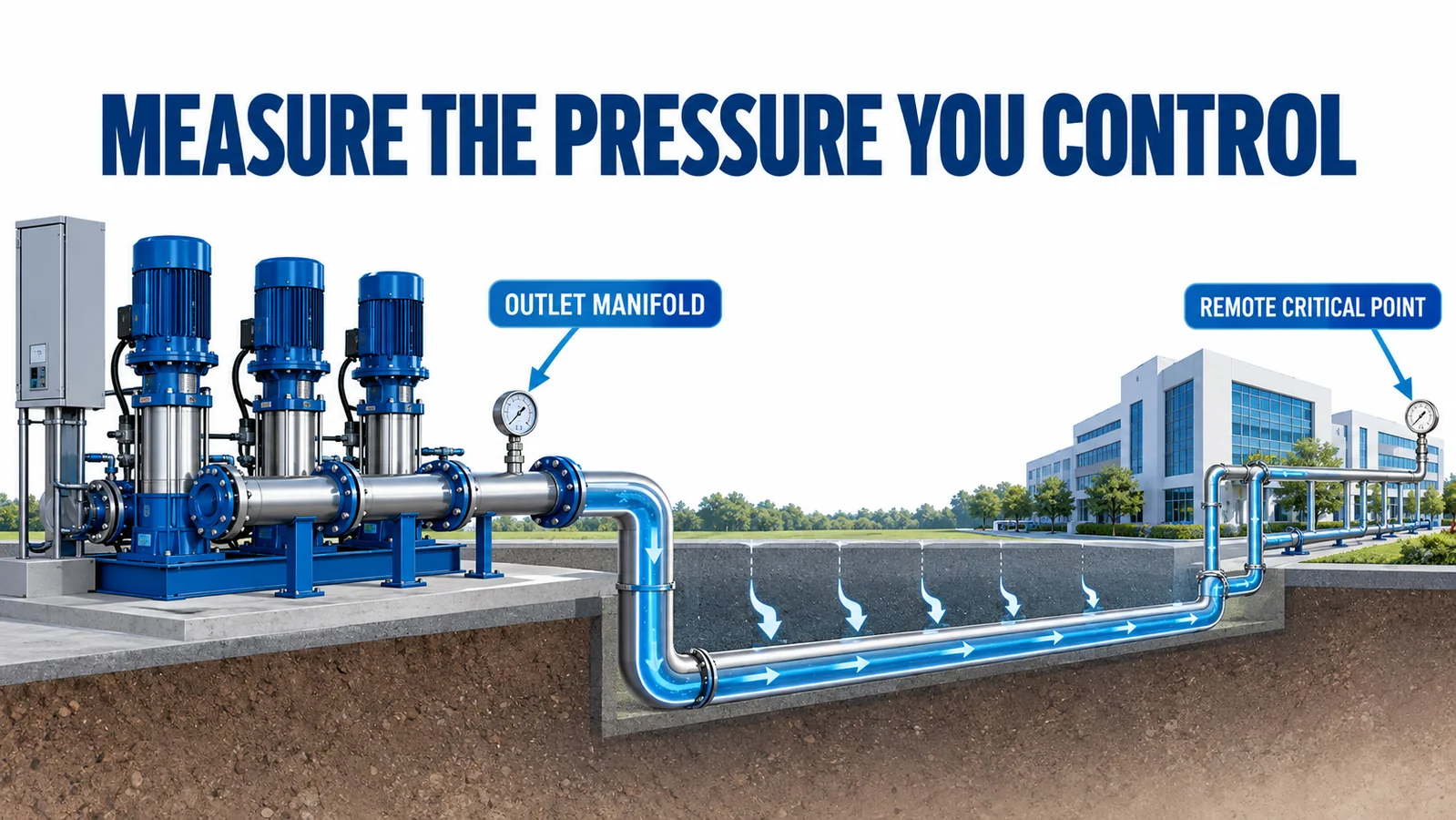
The feedback sensor should measure the pressure the control system is supposed to hold. That sounds obvious, but three locations can answer different questions.
Outlet-manifold sensing
A transmitter on the common discharge manifold measures pressure close to the pumps. It is easy to wire, inspect and commission. It also gives the controller a direct view of booster discharge pressure. This arrangement is common in packaged booster sets.
The limitation is that pressure at the pump room is not necessarily pressure at the most remote user. Pipe friction, elevation and simultaneous demand can create a large difference. A constant outlet pressure can coexist with a low pressure at a critical fixture.
Remote critical-point sensing
A remote sensor can regulate pressure at the hydraulically critical point. This can reduce excessive pressure near the pumps while protecting service at the far end. It also adds cable, communications, accessibility and failure-mode questions. The controller needs a defined fallback if the remote signal is lost.
Local and remote sensors together
Some systems use the manifold sensor for primary control and a remote measurement for reset, optimization or supervision. Define which value owns the loop. Two sensors should not issue competing speed commands without an intentional control strategy.
Should the Sensor Measure Gauge or Absolute Pressure?
Water-supply setpoints are normally expressed as pressure relative to local atmosphere, so gauge pressure is the usual starting point. An absolute sensor includes atmospheric pressure in its reading and can create an apparent change as weather or elevation changes, even if the useful gauge pressure is unchanged.
A sealed-gauge reference can be useful in higher ranges or sealed packages, but the difference between sealed gauge and true vented gauge should be understood. At low pressure spans, atmospheric variation can become material. Record the exact reference in the controller specification and calibration procedure.
How Should the Pressure Range Be Chosen?
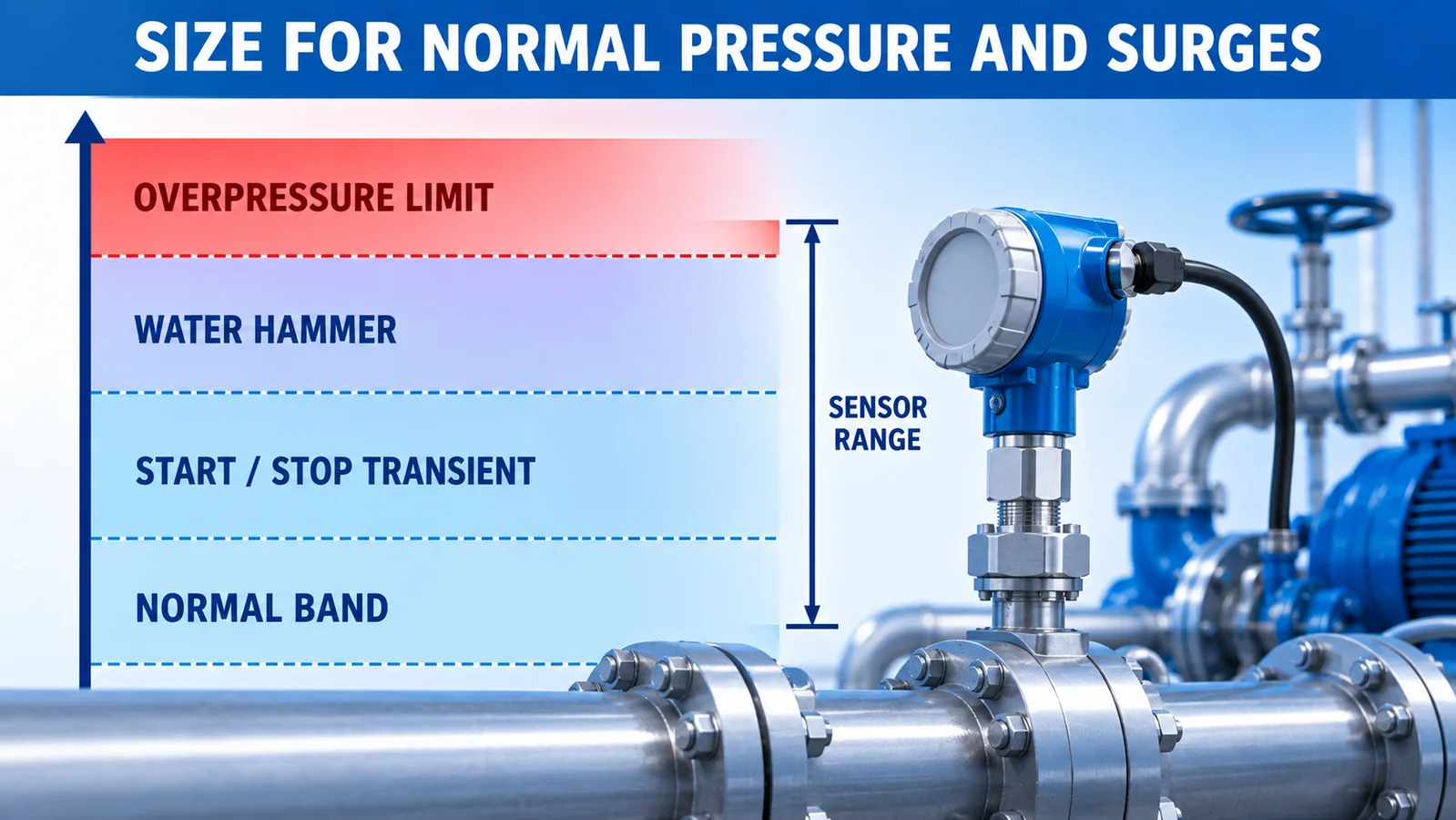
Do not select range from the setpoint alone. Record at least:
- minimum pressure when pumps are stopped or the inlet is isolated;
- normal control band at low and high demand;
- maximum pressure at shutoff or minimum flow;
- pump start and stop transients;
- credible valve-closure and check-valve events;
- hydrostatic pressure from elevation;
- test and cleaning pressure;
- sensor safe overload and burst limits.
A sensor should not operate continuously at its mechanical limit. At the same time, a range several times larger than every credible pressure can waste ADC resolution and enlarge a percent-of-full-scale error in engineering units.
For example, if a system normally controls around 500 kPa but can reach 750 kPa during a verified transient, a 600 kPa sensor would be mechanically questionable even though the setpoint fits. A much larger 6 MPa device would survive but may provide unnecessary span. The final choice comes from the verified transient envelope and product-specific overload table.
How Do Water Hammer and Pulsation Affect Selection?
Water hammer is a fast pressure event caused by a rapid change in liquid velocity. Check valves, fast solenoids, abrupt pump staging and sudden demand changes can create peaks that a slow controller trend never displays. The sensor still experiences the event mechanically.
Use hydraulic measures first: appropriate valve timing, controlled VFD ramps, correctly selected pressure vessels, non-slam check valves and sound piping design. A snubber or restrictor can protect a transmitter and reduce pulsation, but it also changes the dynamic response and can clog. Treat it as an engineered component rather than a universal accessory.
Do not infer surge survival only from the measurement range. Safe overload, burst pressure, cycle life and diaphragm construction are separate specifications. If the supplier’s overload table depends on range, use the exact ordered range.
Which Output Is Best for a Booster Controller?
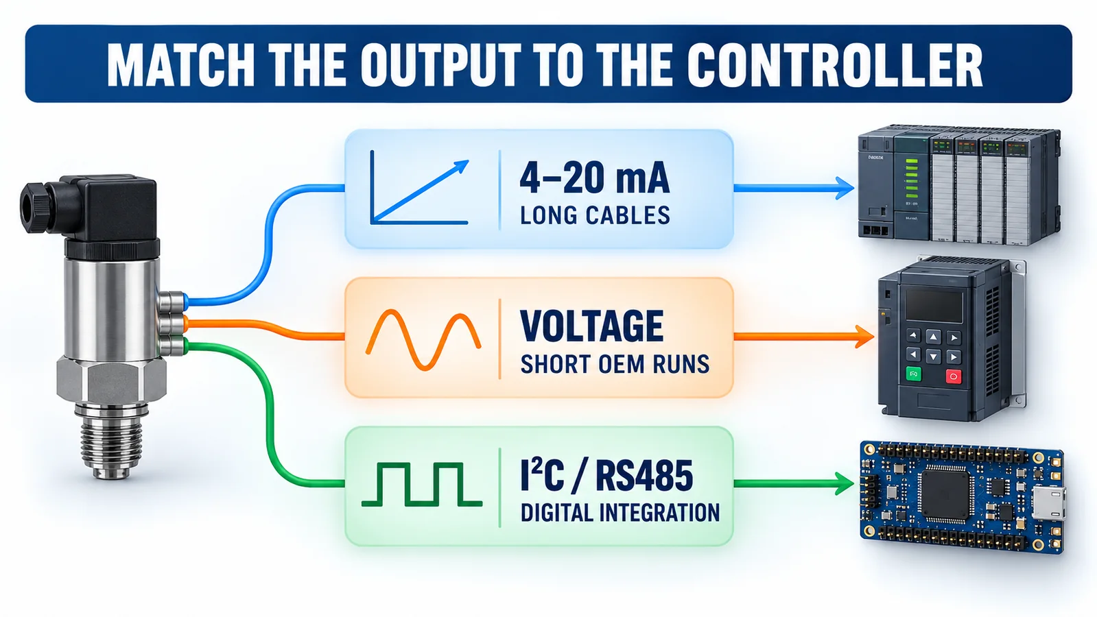
4–20 mA
A current loop is convenient for industrial PLC analog inputs and longer cable runs. A live zero can help distinguish some wiring faults from a valid zero reading. Verify loop supply, total resistance, input scaling, grounding and fault-current behavior.
Conditioned voltage
Outputs such as 0.5–4.5 V or 0–10 V can be straightforward in compact equipment. Confirm the supply tolerance, common ground, input impedance, cable length and whether the output is ratiometric. A voltage interface that works on a short bench cable may be more vulnerable in a noisy plant.
I²C or RS485
Digital outputs can reduce analog scaling work and may provide diagnostic data. I²C is normally an embedded-board interface rather than a long field bus. RS485 is more appropriate for longer multidrop industrial links when protocol, termination, isolation and fault handling are defined.
Der pressure sensor vs transducer vs transmitter guide explains why a conditioned transmitter and a raw sensing core create different integration work.
How Fast Should the Sensor Be?
The pressure transmitter should be fast enough to show relevant demand changes and abnormal events, but the loop does not benefit from feeding every impeller ripple into the VFD command. The complete dynamic path includes:
- hydraulic response of pipes, tanks and valves;
- sensor and pressure-port response;
- signal filtering;
- PLC scan and input update time;
- PID calculation;
- VFD acceleration and pump response.
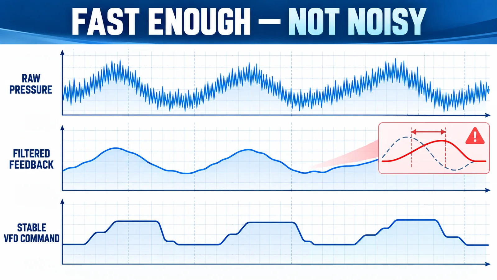
Too little filtering can cause speed hunting. Too much filtering adds phase lag, slows recovery and can make tuning unstable. Start from measured system trends, choose a deliberate sample and filter period, then tune the controller under low, medium and high demand. Sensor response time is only one part of the result.
What Accuracy Is Actually Needed?
Translate accuracy into pressure units. If a ±0.5% FS transmitter has a 1 MPa span, that term alone corresponds to ±5 kPa. Then consider zero error, temperature effects, long-term stability, input-card error and installation effects.
The practical requirement is usually tied to the acceptable control band. A very accurate sensor cannot compensate for a poorly placed tap or an oscillating hydraulic loop. Conversely, a stable, correctly ranged sensor can support good control even when the application does not need laboratory-grade accuracy.
Use the FS versus reading accuracy guide to normalize supplier claims before comparing alternatives.
Mechanical and Environmental Requirements
Confirm every pressure connection and seal. G, NPT and metric threads are not interchangeable. Review the NPT- oder G-Gewindeführung before specifying adapters or sealant.
For water service, verify wetted materials against actual water chemistry, treatment chemicals and temperature. “Stainless steel” is not a complete compatibility statement. Include diaphragm grade, port, welds, seals and any installation gasket.
Mount the transmitter where it can be isolated and serviced without creating a trapped air pocket or dead leg. Protect connectors from condensation and washdown. Support the cable, avoid tightening through the electrical housing, and follow the pressure sensor installation guide.
How Do WPCK07 and WPCK63 Fit?
Die jetzige Winsen WPCK07 page lists a diffused-silicon transmitter with gauge, absolute and sealed-gauge options, a broad configurable range, a 316L diaphragm and multiple conditioned outputs including 4–20 mA, voltage, I²C and RS485 variants. This makes it a candidate when a field-ready interface and broader output choice are required. The exact ordered configuration must be confirmed.
Die jetzige WPCK63 page describes a compact diffused-silicon transmitter from -100 kPa to 6 MPa with a 316L diaphragm. Its current page lists 0.2–2.3 V or I²C, fast response and IP68 construction. It can suit a compact integrated booster design when its interface, range and mechanical configuration match the controller.
These are not interchangeable merely because both use diffused-silicon sensing. Compare pressure range, output, supply, accuracy definition, overload, thread, connector, ingress protection and cable arrangement on the quotation and drawing.
Booster Pump Commissioning Workflow
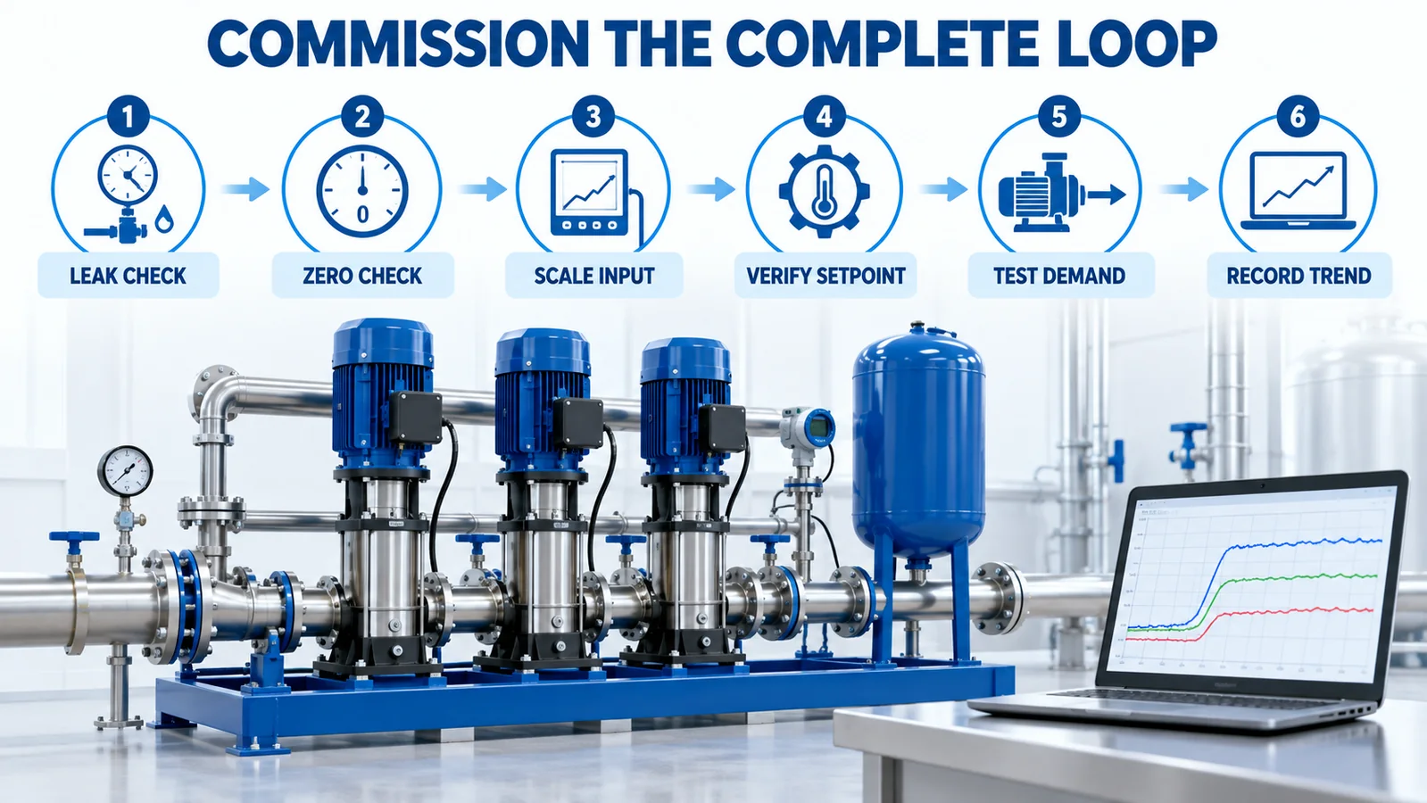
- Confirm the transmitter model code, pressure reference, range and output.
- Isolate and leak-test the process connection.
- Check zero at a known pressure condition.
- Apply one or more reference pressures and confirm PLC scaling.
- Verify engineering units, decimal position and alarm limits.
- Start one pump and observe the direction of feedback and VFD command.
- Test low, normal and high demand without exceeding system limits.
- Stage additional pumps and examine pressure steps.
- Test sensor-disconnect and out-of-range fault behavior.
- Record pressure, speed, pump status and demand trends as the baseline.
Troubleshooting Table
| Symptom | Likely checks |
|---|---|
| Pressure hunts around setpoint | Tap pulsation, insufficient or excessive filtering, PID gains, tank condition, valve interaction |
| Controller shows a fixed value | Supply, loop continuity, input configuration, cable fault, frozen digital data |
| Reading differs from gauge | Reference type, range scaling, tap elevation, trapped air, gauge accuracy |
| Pressure drops at remote users | Sensor location, pipe loss, demand, setpoint reset strategy |
| Repeated zero shift | Mechanical stress, temperature, vent blockage, moisture, permanent overpressure |
| Sensor fails after pump events | Surge pressure, snubber condition, valve closure, overload rating, installation torque |
RFQ Checklist
Provide the supplier with normal pressure, maximum credible pressure, vacuum possibility, surge evidence, medium, temperature, reference type, required accuracy, output, supply, cable distance, connector, thread, ingress protection, vibration, annual volume and applicable approvals. Also state whether the device will be a serviceable field transmitter or part of an OEM assembly.
FAQ
Can a pressure switch replace a continuous transmitter?
A switch can provide discrete high or low status, but variable-speed constant-pressure control normally needs a continuous feedback value. A separate safety switch may still be used for an independent interlock.
Should the sensor be installed before or after the check valve?
It should measure the controlled hydraulic node. On many booster sets this is the common discharge manifold after individual pump check valves, but the system designer must confirm the intended control boundary and service isolation.
Does a faster response always improve control?
No. The useful response is set by the entire hydraulic and control loop. Very fast unfiltered data can expose pump ripple that drives unnecessary VFD changes.
What should happen if the sensor signal fails?
Define a safe fault strategy: alarm, controlled stop, limited-speed fallback or transfer to a redundant measurement. The choice depends on water-supply criticality and system risk.
Abschluss
A reliable booster pump pressure sensor is selected as part of a closed-loop system. Measure the pressure that matters, size the range from normal and transient conditions, match the output to the controller, and commission the complete loop under realistic demand. For an OEM configuration review, contact Winsen with the hydraulic envelope and controller interface rather than only a target setpoint.
