
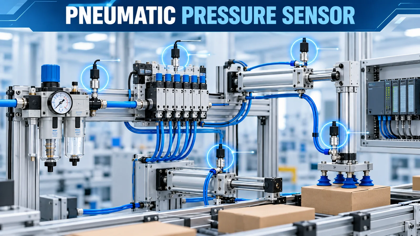
A pneumatic pressure sensor converts compressed-air or vacuum pressure into an electrical value used by a PLC, controller or embedded system. The correct selection begins with the event that must be detected: inadequate plant air, regulator drift, pressure loss at a valve manifold, actuator supply collapse, vacuum-grip failure or a slow leak.
Measuring the main header alone is rarely enough. An automated machine can have acceptable supply pressure while a clogged filter, undersized tube, sticky valve or high instantaneous flow causes the local actuator pressure to fall during the cycle.
What Is the Short Selection Answer?
Choose a gauge-pressure sensor for ordinary positive-pressure pneumatics and a vacuum or compound-range device when the application crosses atmospheric pressure. Put it near the point whose pressure determines machine success. Select range from normal pressure, temporary drops and maximum credible supply; then match the output to the PLC or OEM electronics.
For a continuous trend or closed-loop calculation, use a conditioned transmitter. For a simple pass/fail interlock, a pressure switch with a defined PNP/NPN output and hysteresis may be more direct. Do not assume a transmitter is a drop-in replacement for a switch.
Le Festo SDE5 documentation illustrates common pneumatic uses including compressed-air monitoring, regulator monitoring, vacuum detection and object detection by back pressure. Those categories are a useful way to define the job before choosing a device.
Where Should Pressure Be Measured?
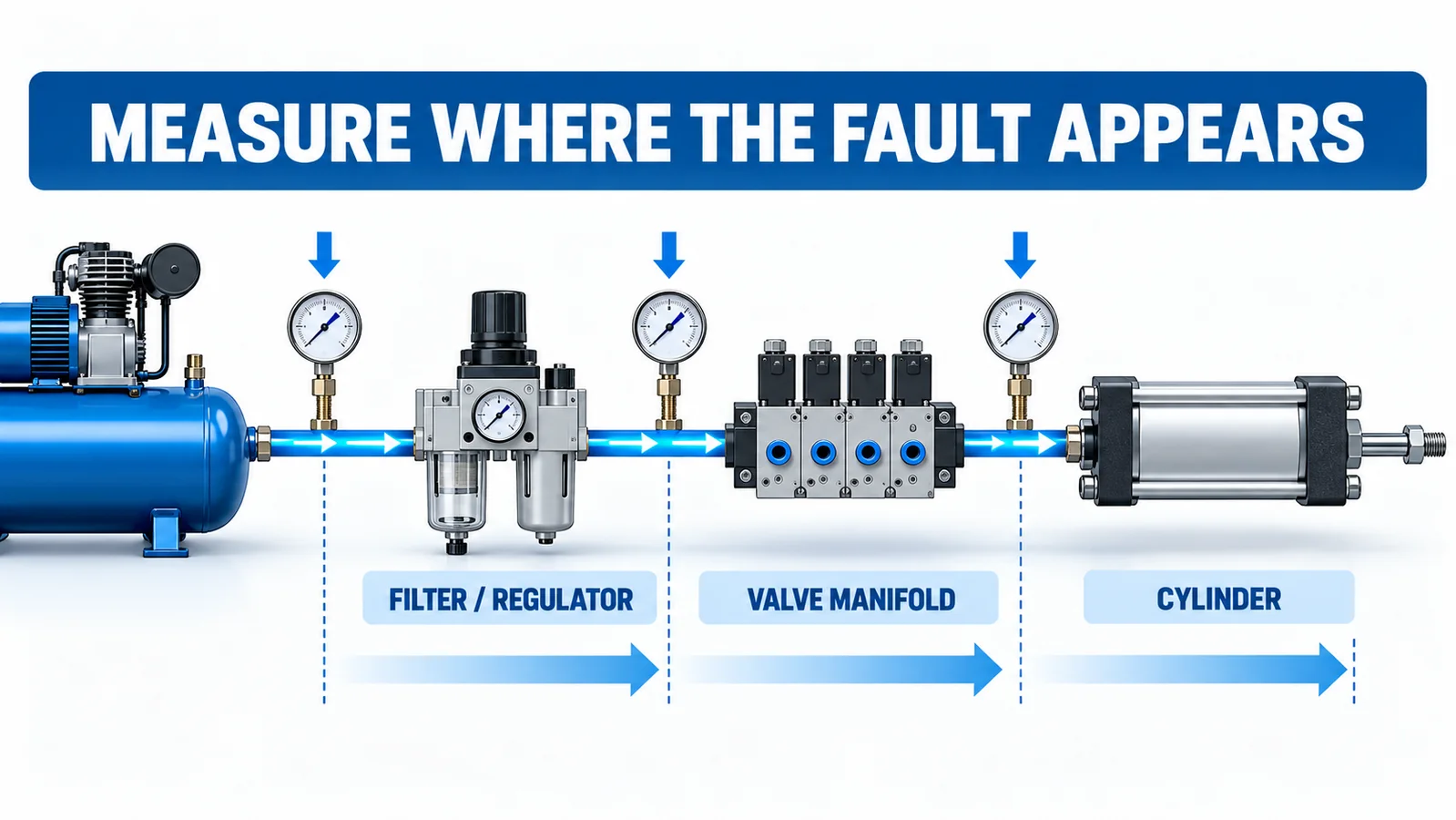
Plant header
A header sensor shows the utility available to a group of machines. It supports compressor control, energy management and low-supply alarms. It does not reveal every local restriction downstream.
After the filter-regulator unit
This point verifies the regulated machine supply and can reveal a clogged filter, incorrect regulator setting or supply collapse. If the machine has separate pressure zones, one sensor may not represent all of them.
Valve manifold inlet
Manifold pressure is closer to the actuators and captures losses in upstream tubing. It is useful where multiple valves share a compact air island.
Near a critical actuator or vacuum cup
Point-of-use measurement can detect a short pressure loss hidden at the main inlet. It also experiences faster transients and may need more careful tubing, response and filtering design.
The principle is simple: measure where the failure appears, not merely where installation is convenient.
Gauge, Absolute, Vacuum or Differential?
Gauge pressure is referenced to atmosphere and is the normal choice for shop-air regulators, cylinders and manifolds. Vacuum handling often uses negative gauge pressure or a compound range spanning vacuum to positive pressure.
Absolute pressure is useful when the process must be independent of atmospheric variation, but it is not automatically better for pneumatics. A controller expecting gauge units will appear offset if connected to an absolute sensor.
Differential pressure is appropriate across a filter, restriction or flow element when the difference between two ports matters. It is not the same as measuring the positive line pressure. Define port polarity and common-mode pressure before specifying a differential device.
How Should the Range Be Selected?
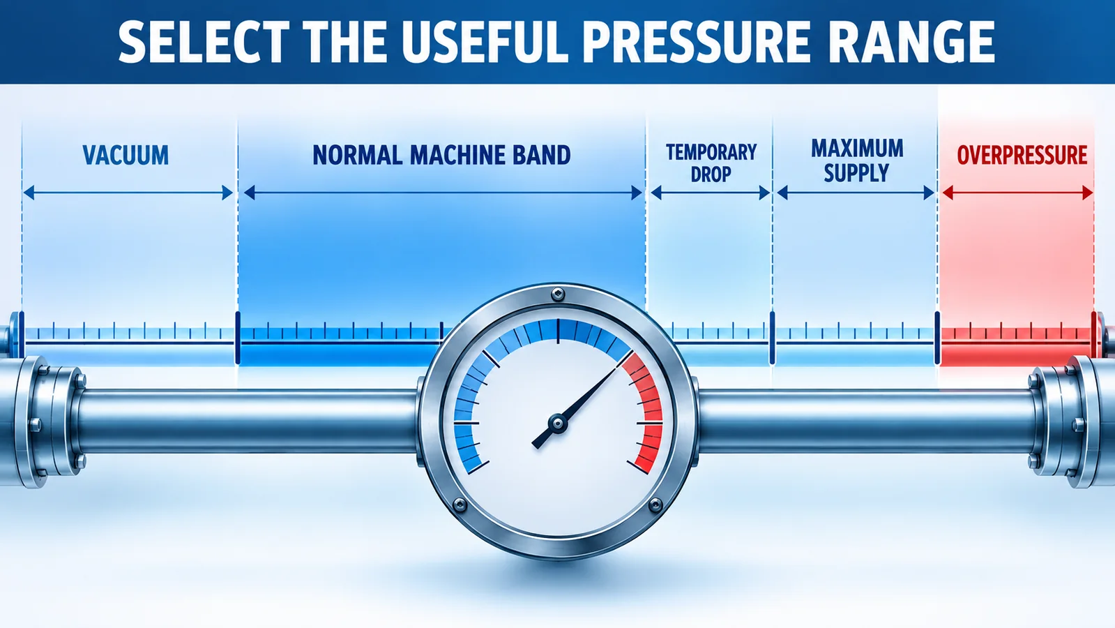
Record the normal regulator setting, minimum pressure needed for successful actuation, transient pressure during the highest-flow event, maximum upstream supply, possible vacuum and abnormal overpressure. Select a range that covers the verified envelope while using enough of the span for useful resolution.
A 0–10 bar range may be practical on a nominal 6 bar machine, but it is not automatically correct for a low-pressure gripper or a vacuum circuit. A broad range makes small changes less visible, especially when accuracy is specified as percent of full scale.
Also distinguish proof, safe overload and burst pressure. The maximum reading on a display is not necessarily the maximum pressure the device can safely experience. Check reverse pressure if a vacuum line can suddenly return to positive pressure.
Continuous Transmitter or Pressure Switch?
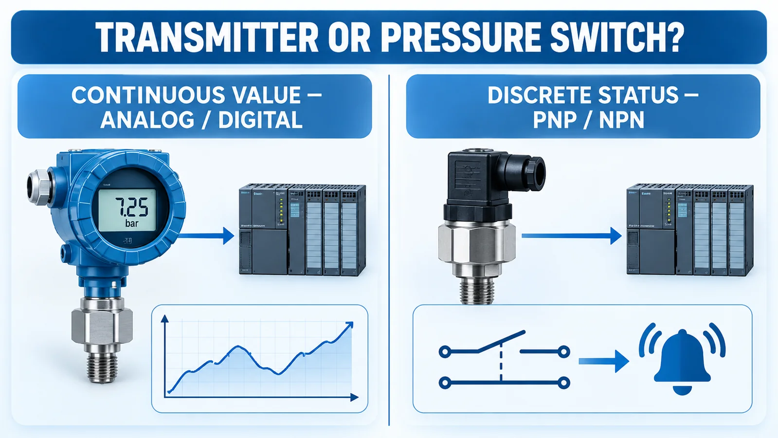
Continuous transmitter
A transmitter provides an analog or digital value. It supports trending, multiple software thresholds, pressure-rate calculations, predictive maintenance and correlation with cycle state. It requires an analog input or digital interface and suitable software.
Electronic pressure switch
A switch produces a discrete status when pressure crosses a threshold. Industrial versions may offer PNP or NPN outputs, adjustable hysteresis, window functions and teach-in. It is convenient for a direct machine interlock but provides less process detail unless it also has an analog or communication output.
Mechanical switch
A mechanical switch can be simple and independent but may have wider hysteresis, limited cycle life or less diagnostic visibility. Its suitability depends on the safety function and required reliability.
If the function is safety-related, follow the machinery risk assessment and applicable architecture. Do not rely on a general-purpose transmitter plus ordinary PLC logic as a safety function without the required design and validation. ISO 4414:2010 provides general rules and safety requirements for pneumatic fluid-power systems and components.
Response Time, Filtering and Anti-Chatter
Pneumatic pressure changes can be shorter than the PLC scan or much longer than a complete machine cycle. Define the duration that constitutes a real fault.
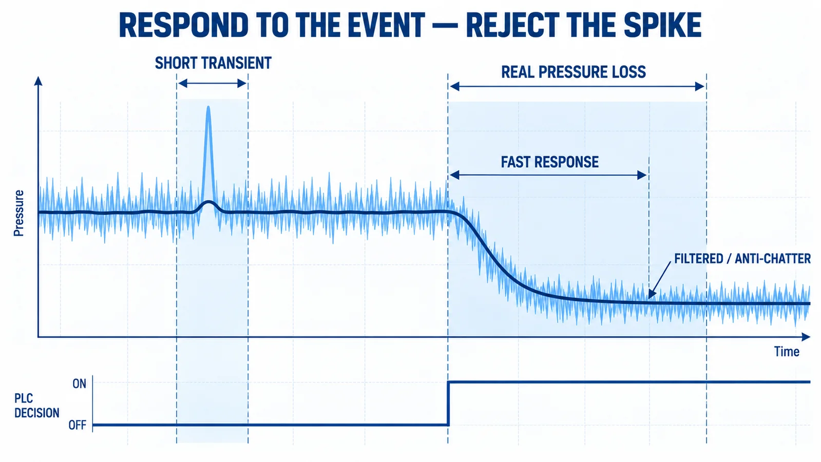
Le SMC ISE10 catalog illustrates why response and anti-chattering are application choices: a large cylinder or ejector can create a temporary pressure drop that should not always be treated as a failure.
Use a fast sensor when a short event is meaningful, but coordinate it with input-update time and PLC logic. Filtering can reject valve spikes and compressor ripple. Excessive filtering can hide a genuine loss of grip or delay a stop command.
A practical rule is to log raw pressure during representative cycles, determine the normal transient envelope, then set response, filter and threshold delay outside that envelope while remaining inside the maximum fault-detection time.
Which Output Fits the Machine?
4 à 20 mA
Useful for longer cables and industrial analog inputs. Verify loop supply and scaling. A 4 mA live zero can support wire-fault diagnostics, but only if the input and software distinguish under-range current.
Voltage output
0.5–4.5 V, 0–5 V or 0–10 V can fit compact machines. Confirm supply, ground offset, input impedance and noise. Ratiometric outputs require compatible measurement architecture.
I²c
I²C is suited to short embedded connections. It is not a general long-distance factory bus. Define pull-ups, logic levels, addressing, update rate and recovery from a locked bus.
PNP/NPN switching output
PLC digital inputs may require sourcing PNP or sinking NPN behavior. A pressure transmitter with only voltage, current or I²C output does not provide this automatically. Use a controller input and logic conversion or select a purpose-designed switch.
Accuracy, Repeatability and Threshold Margin
For machine interlocks, repeatability near the threshold can matter more than a very small room-temperature accuracy claim. Leave margin between normal pressure variation and the fault limit. Include sensor accuracy, regulator tolerance, temperature drift, installation effects and PLC input error.
If a machine needs at least 5.0 bar at a cylinder but normally falls to 5.1 bar during acceleration, a threshold at 5.0 bar has almost no process margin. The design should address supply and restriction before relying on a more accurate sensor.
Le pressure sensor accuracy guide explains how percent-of-full-scale errors translate into engineering units.
Air Quality, Condensate and Media Compatibility
Compressed air can contain water, compressor oil, particles and cleaning chemicals. Verify the sensor’s permitted medium and wetted materials. A device approved for clean, non-corrosive gas is not automatically suitable for wet or chemically contaminated air.
Install and maintain filtration and water separation appropriate to the machine. Avoid a pressure tube low point that collects condensate unless a drain is intentional. Protect a vented gauge reference from oil mist and washdown without sealing the vent.
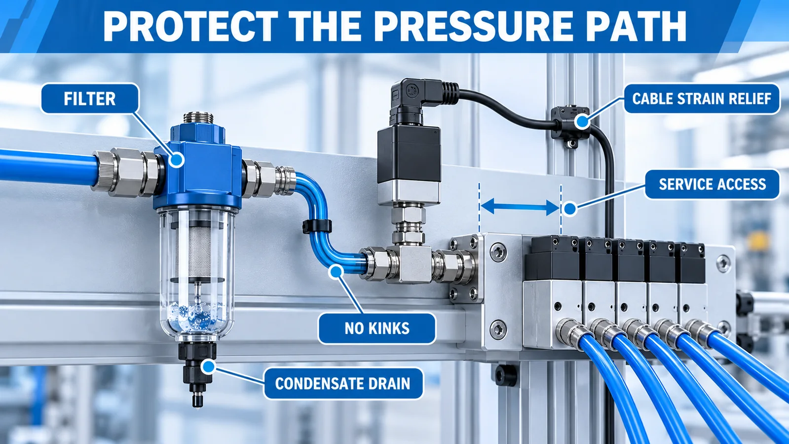
Tubing should be short enough for the required response, protected from kinks and abrasion, and large enough not to create an unintended restriction. Support the cable and connector against repeated machine movement. The installation mistakes guide covers thread, torque, routing, vent and commissioning risks.
How Do WPCH01 and WPCK63 Fit?
Le courant Winsen WPCH01 page describes a ceramic pressure transmitter with 0.5–4.5 V, 4–20 mA or I²C output options, a current page range of 0.2–40 MPa, response below 1 ms and IP67 construction. It is a conditioned transmitter candidate for positive-pressure gas or liquid applications when the exact range, thread, seal and output match the machine. Its lower range boundary means it is not the default choice for every low-pressure or vacuum circuit.
Le courant Page WPCK63 lists a compact diffused-silicon transmitter from -100 kPa to 6 MPa, gauge/absolute/sealed-gauge references, 0.2–2.3 V or I²C output, ≤1 ms response, 316L diaphragm and IP68 construction. It can fit compact positive-pressure or vacuum-capable OEM designs when the media and interface are validated.
Neither page identifies a PNP/NPN switching output. If the machine expects a digital switch input, plan the conversion in the controller or select a pressure switch whose output is specified for that interface.
Commissioning Workflow
- Confirm model, range, pressure reference, output and supply.
- Inspect tubing, thread seal, filter and regulator.
- Check zero at a known atmospheric or vacuum condition.
- Apply a reference pressure and confirm PLC scaling.
- Run the machine slowly and identify each pressure event.
- Test the highest-flow simultaneous motion.
- Establish normal minimum and maximum bands.
- Set threshold, hysteresis, filter and delay from recorded data.
- Simulate a supply loss, restricted tube and disconnected signal.
- Store the pressure trace with valve command and actuator feedback.
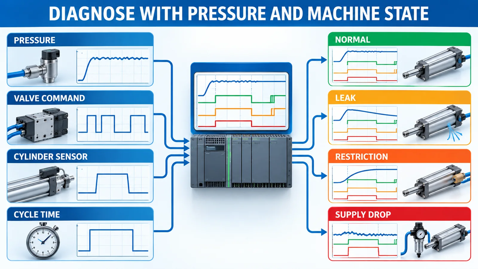
Troubleshooting Table
| Symptôme | Checks |
|---|---|
| Low pressure only during motion | Tube diameter, valve flow, filter restriction, regulator droop, simultaneous demand |
| Frequent false alarm | Normal transient duration, filter, hysteresis, PLC scan, threshold margin |
| Slow pressure recovery | Leak, exhaust restriction, regulator capacity, long small-bore tube |
| Vacuum grip fails intermittently | Cup seal, ejector supply, contamination, part porosity, sensor location |
| Reading changes after washdown | Connector ingress, vent blockage, condensate, ground fault |
| Header normal but actuator weak | Local restriction, valve fault, kinked tube, point-of-use pressure |
RFQ Checklist
Specify pressure mode, normal and maximum range, vacuum, medium and air treatment, temperature, response requirement, threshold logic, output, supply, PLC input, cable length, port, connector, ingress protection, vibration, washdown, annual volume and required approvals. State whether you need a continuous transmitter, a discrete switch or both.
FAQ
Is a pneumatic sensor installed before or after the regulator?
Install it at the point that answers the control question. Before the regulator measures supply; after it verifies the regulated machine pressure. Critical machines may monitor both.
Can a liquid pressure transmitter measure air?
Possibly, if its pressure range, reference, wetted materials, port, response and manufacturer-approved media fit. Do not infer gas suitability from housing appearance.
How close should it be to the actuator?
Close placement reduces the chance that tubing dynamics hide the local event, but it may increase vibration, motion and wiring exposure. Balance measurement fidelity with serviceability.
Is one pressure sensor enough for a whole machine?
It may be enough for supply supervision. Separate pressure zones, vacuum circuits or critical actuators may need additional measurements.
Conclusion
A reliable pneumatic pressure sensor is selected around the machine event, measurement point and controller interface. Measure locally when local pressure determines success, distinguish continuous transmitters from switches, and set response and filtering from real cycle data. For an OEM review, contact Winsen with the complete pneumatic and electrical specification.
