
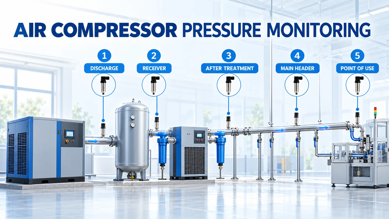
An air compressor pressure sensor should be selected and installed for a defined job. A sensor at the compressor discharge helps assess machine output. A receiver sensor supports storage and control. A sensor after the dryer and filters shows treatment loss. A header sensor represents the plant supply, while a sensor at a critical user shows whether the process receives enough pressure under load.
The working-pressure target should begin at the point of use, then add measured or validated losses through treatment and distribution plus a justified control allowance. The compressor’s load, unload, cut-in or cut-out values must come from the specific compressor and system documentation. A transmitter’s measurement span is not a control setpoint, and a safety relief valve is an independent protection device.
| Question | Best starting measurement | Why it matters |
|---|---|---|
| Is the compressor producing the expected pressure? | Discharge, at an approved tapping point | Separates machine behavior from downstream losses |
| Is stored air buffering demand? | Receiver | Shows the pressure available to the control system and demand peaks |
| How much pressure is lost in treatment? | Before and after dryer/filter stages | Reveals restrictions and maintenance needs |
| Is the plant supply stable? | Main header | Provides a common reference for distribution performance |
| Does the process receive adequate pressure? | Critical point of use | Captures downstream loss during actual demand |
What Does an Air Compressor Pressure Sensor Do?
A pressure transmitter converts pneumatic pressure into a continuous electrical or digital signal. The controller, PLC, data logger or monitoring platform can display it, trend it, alarm it and use it in permitted control logic. Continuous data is valuable because the same average pressure can hide very different cycling, pressure loss and demand patterns.
Gauge, switch, transmitter and relief valve
These devices share a pressure connection but have different responsibilities:
- UN jauge gives local indication for operators and service work.
- UN pressure switch changes a discrete contact at a threshold. Small reciprocating compressors often use a switch for start and stop control.
- UN émetteur de pression sends a continuous value. Modern controllers can use it for load/unload control, variable-speed regulation, sequencing and diagnostics.
- UN relief valve protects against overpressure. Its setting, certification and maintenance follow the receiver and equipment safety requirements; it is not a normal control adjustment.

A plant may need all four. Replacing a failed switch with a transmitter does not automatically reproduce the original safety or control function. The input hardware, logic, diagnostics and fail state must be engineered as a system.
Pressure reference matters
Compressed-air systems commonly display pression de mesure, relative to local atmosphere. Absolute pressure is referenced to vacuum and may be needed for thermodynamic calculations, altitude-sensitive work or specific controls. Sealed-gauge devices use a sealed reference and can suit higher pressure ranges, but their behavior differs from a vented gauge sensor as ambient pressure changes.
Confirm that the sensor reference, controller scaling and engineering calculations use the same basis. A value shown as “bar” without g, a or another reference can create commissioning errors.
Where Should Pressure Be Measured in a Compressed-Air System?
One sensor cannot separate compressor output, storage behavior, treatment loss, distribution loss and process demand. Place sensors so that differences between readings have a clear physical meaning.

1. Compressor discharge
A discharge-side measurement can verify compressor output and help correlate pressure with load state. This location may also have the highest temperature, vibration and pulsation. Use only an approved tapping point and keep the sensor within its media-temperature, ambient-temperature and dynamic-pressure limits. A cooling length, remote mount, snubber or other conditioning may be appropriate when the equipment manufacturer permits it.
2. Air receiver
Receiver pressure shows the stored-air condition seen by many start/stop or load/unload controls. The receiver buffers short demand peaks and slows pressure change. Receiver volume, demand profile, compressor capacity and control band all affect cycling; a noisy or rapidly changing receiver signal deserves investigation rather than aggressive software filtering alone.
3. Before and after air treatment
Dryers, separators and filters create pressure loss. Measurements across a treatment train help distinguish insufficient compressor pressure from a restriction. For a filter, a dedicated differential-pressure measurement is often more useful than subtracting two unsynchronized or differently ranged gauge transmitters.
4. Main header
The header is a useful plant-supply reference after treatment. Compare it with receiver pressure to quantify treatment and compressor-room loss. Trend it with total flow and compressor state to see whether a pressure fall comes from demand, capacity, control behavior or a restriction.
5. Critical point of use
The pressure that matters to production is the pressure available at the equipment while it is consuming air. A compressor-room gauge can look normal while a long branch, undersized hose, regulator, quick coupling or local filter starves the process. Measure near the critical machine and record the operating state and flow demand.
How Do You Select the Pressure Transmitter?
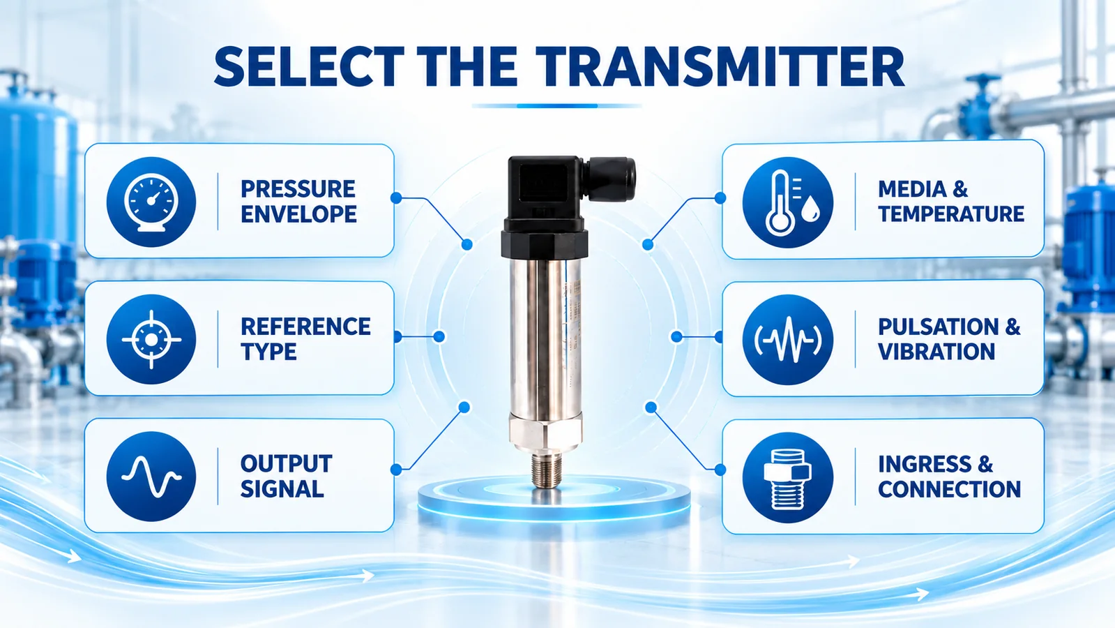
Choose the transmitter around the complete operating envelope and installation, not only the normal pressure shown on a gauge.
Pressure range and overload
Document normal minimum and maximum pressure, control thresholds, shutdown conditions and credible pulsation or surge. Select a calibrated range that covers required operation with suitable margin while retaining useful resolution. Check proof and burst limits separately: a published measurement range does not state how a device behaves after an overload.
Accuracy stated as a percentage of full scale depends on the selected range. With a ±0.5% FS specification, a 16 bar full-scale transmitter has a larger absolute error allowance than a 10 bar version. Oversizing the range can therefore weaken control and diagnostic resolution. The guide to pressure sensor accuracy in %FS and %reading explains the calculation.
Pressure reference and output
Gauge reference is common for plant air, but confirm the project requirement. For long industrial cable runs, 4–20 mA is widely used because the current signal is robust and provides a live-zero convention. Voltage or digital outputs may fit embedded compressor electronics when the supply, cable length, grounding, input circuit and protocol are designed together.
The controller must use the exact lower and upper range values configured in the transmitter. A 4–20 mA signal scaled as 0–10 bar will report the wrong pressure if the installed device is actually 0–16 bar.
Media, temperature and condensate
The sensor may contact moist compressed air, compressor carryover or cleaning residues. Confirm diaphragm, port and seal compatibility. Keep process and ambient temperatures within the configured limits. Install the tapping so condensate does not collect where it can freeze, block the port or create a liquid head error. Provide drainage and isolation as permitted by the system design.
Pulsation, vibration and response
Fast response is useful for control and transient diagnosis, but it can expose every compressor pulse and mechanical disturbance. Do not solve a poor pressure tapping only by averaging the signal. First assess location, mounting, impulse path, electrical noise and the controller sample rate. If damping is needed, define which events must remain visible.
Ingress protection and mechanical connection
The enclosure, cable entry and connector must suit oil mist, dust, washdown, condensation and outdoor exposure. Mount the device and cable so vibration is not concentrated at the pressure port. Verify thread form, sealing method and torque; NPT and G threads are not interchangeable simply because their nominal sizes look similar. See the NPT versus G pressure-sensor thread guide.
How Is the Required System Pressure Determined?
Start downstream and work toward the compressor. The practical relationship is:
System pressure target = point-of-use requirement + treatment loss + distribution loss + justified control allowance

Le point-of-use requirement comes from the production equipment under its actual flow condition. The treatment loss includes separators, dryers and filters. The distribution loss includes pipe, fittings, valves, hoses, regulators and couplings. The control allowance accounts for the pressure band and response needed to keep the critical user above its requirement.
Measure losses during representative demand. A nameplate requirement and a no-flow pressure reading do not reveal the dynamic loss through the final hose and coupling. Increasing compressor pressure to hide a local restriction can increase energy use and leakage while leaving the root cause in place.
A variable-based example
Let the required pressure at a critical machine be Puse. Let measured treatment loss at design flow be ΔPtreatment, distribution loss be ΔPdistribution, and the justified control allowance be Pallowance.
Ptarget = Puse + ΔPtreatment + ΔPdistribution + Pallowance
This equation produces an engineering requirement, not permission to change the compressor. Compare the result with compressor capability, receiver rating, relief-device requirements and the manufacturer’s approved control range. The equipment manual and responsible engineer define final settings.
What Are Load, Unload, Cut-In and Cut-Out Setpoints?
The names depend on compressor type and control method, but each defines a state transition within an allowed pressure range.
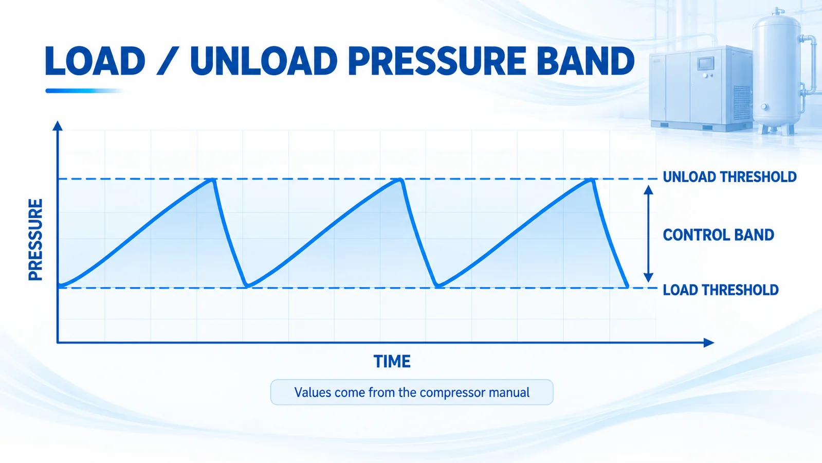
Load and unload control
In a load/unload system, the compressor produces air when pressure falls to the load threshold. It unloads when pressure rises to the unload threshold. The difference is the control band. A band that is too narrow can cause excessive cycling; one that is too wide may create unacceptable pressure variation. Receiver volume and demand dynamics also matter.
Cut-in and cut-out control
Smaller compressors may stop at cut-out pressure and restart at cut-in pressure. A pressure switch often performs this function. The differential must provide adequate off time and stay within the manufacturer’s permitted settings. Frequent starts may point to inadequate storage, leaks, high demand, a failed check or unloader function, or inappropriate settings.
Variable-speed and sequenced systems
A variable-speed compressor can regulate around a target, while a multiple-compressor plant may use a master controller to sequence machines. Local compressor settings, system targets and backup thresholds must be coordinated. Independent adjustments can make machines fight each other, operate inefficiently or leave inadequate reserve capacity.
There is no universal set of pressure values that is safe for every compressor. Use the specific compressor, receiver and system documentation. Never use an article to reset a safety relief valve.
Which Installation Details Prevent Bad Readings?
Good measurement begins before the signal reaches the PLC:
- Use a pressure tapping approved for the machine or pipe and located away from a turbulent dead leg where possible.
- Provide a rated isolation method so the transmitter can be serviced safely.
- Prevent condensate pockets, freezing and blocked passages. Follow the site’s drainage and pressure-safety procedures.
- Support the transmitter or remote line where vibration could load the process thread.
- Route signal cable away from motor and variable-frequency-drive power conductors; follow grounding and shielding instructions.
- Protect outdoor and washdown connections with the correct connector, gland, drip loop and enclosure practice.
- Configure engineering units and range endpoints at the controller before applying alarms or control logic.
- Label the measurement point and record the valve position, range, output, serial or asset ID and calibration date.
How Do You Troubleshoot an Unstable or Implausible Signal?
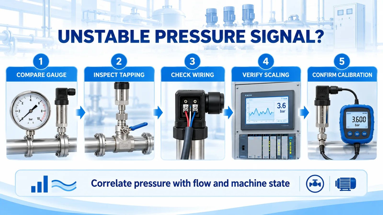
Work from independent evidence through the pressure path and electrical chain. Do not assume that every fluctuation is a bad sensor.
Compare a local indication
Compare the transmitter with a suitable reference connected to the same pressure point. Two instruments at different locations can legitimately disagree because of pressure loss and pulsation. Record compressor state and demand during the comparison.
Inspect the tapping and isolation path
Check for a partly closed valve, blocked port, condensate, leaks, a damaged snubber or an impulse line that traps liquid. A restricted tapping can create lag; a liquid column can create offset; pulsation can create a rapidly moving value.
Check wiring, supply and scaling
Measure supply and loop conditions using the approved procedure. Inspect terminals, shielding, grounding and cable damage. Confirm the PLC channel type and scaling endpoints. If multiple channels jump when a motor starts, investigate electrical interference and common power or grounding paths.
Confirm calibration and process behavior
If the pressure path and electrical chain pass inspection, compare the transmitter across several known pressure points with an appropriate reference. Also correlate the signal with flow, compressor load state, valve position and power. A repeatable pressure cycle synchronized with machine control may be real process behavior.
How Should the Measurement Be Commissioned?
Before using the signal for control or maintenance decisions:
- Verify model, range, reference type, output, supply, thread and environmental configuration against the order.
- Inspect the tapping, isolation, seals, mounting, cable entry and condensate management.
- Confirm zero and at least one elevated-pressure point with a suitable reference where site procedures permit.
- Verify PLC scaling and engineering units from the field device through the operator display and historian.
- Observe unloaded, loaded and representative demand states. Record the receiver, header and point-of-use pressures together.
- Confirm alarm delays, signal-failure behavior and any permitted control transitions.
- Save a baseline trend with timestamps, machine state and flow context for later troubleshooting.
Which Winsen Pressure Transmitters Can Be Evaluated?
Two Winsen families can be considered for compressor and pneumatic equipment when their configured specifications match the application. The table uses values published on the official product pages; the exact range, output, connection and environmental limits must be confirmed for the ordered version.
| Modèle | Officially published characteristics | Possible evaluation context |
|---|---|---|
| Winsen WPCK07 | Diffused silicon; gauge, absolute and sealed-gauge versions; range family from -100 kPa through 100 MPa; 4–20 mA default with listed voltage options; ±0.5%FS; 316L diaphragm; response to 90%FS in no more than 1 ms; IP65 | Protected compressor-room, control-skid or pipeline locations where the selected range, output, connection and temperature limits fit |
| Winsen WPCK63 | Compact integrated stainless structure; gauge, absolute and sealed-gauge versions; range family from -100 kPa through 6 MPa; published 0.2–2.3 V or I²C outputs with other outputs described as customizable; ±0.5%FS; 316L diaphragm; response no more than 1 ms; IP68 | Compact OEM or moisture-prone pneumatic installations where the exact electrical, mechanical and protection configuration is confirmed |
Neither model number alone confirms fitness for a hot, pulsating compressor discharge or a safety-related function. Share the full application conditions with Winsen before selection. The broader industrial pressure sensor selection guide provides an RFQ framework.
What Information Should an RFQ Include?
Provide enough information to select a specific configuration:
- measurement location and purpose;
- normal, minimum and maximum operating pressure;
- control thresholds and credible surge or pulsation;
- référence à jauge, absolue ou à jauge scellée ;
- air composition, oil carryover, condensate and cleaning exposure;
- process and ambient temperature ranges;
- required accuracy, response and sampling behavior;
- output, supply voltage, controller input and cable length;
- process thread, seal, orientation and isolation arrangement;
- vibration, ingress, washdown and outdoor exposure;
- required approvals, documentation and calibration records.
Foire aux questions
Is an air compressor pressure sensor the same as a pressure switch?
No. A transmitter provides a continuous signal; a switch changes a discrete contact at a threshold. Some electronic controls use a transmitter to implement switching logic, but the controller, diagnostics and fail state are then part of the function.
Should the sensor be installed on the receiver or discharge pipe?
Choose based on the question. The discharge point shows compressor output and may experience more heat and pulsation. The receiver point shows stored system pressure and often supports control. Many systems benefit from both, plus a header or critical-user measurement.
How much higher should compressor pressure be than tool pressure?
There is no universal margin. Determine the tool or process requirement at operating flow, measure treatment and distribution losses, and add only the justified control allowance. Use the compressor manufacturer’s procedure for final settings.
Can a larger sensor range provide more safety margin?
A wider calibrated range may tolerate the required operating envelope, but it can increase absolute error when accuracy is specified as a percentage of full scale. Proof pressure and burst pressure must be checked separately from measurement range.
Why does the point-of-use pressure fall while header pressure looks normal?
The branch may have undersized pipe, excessive hose length, a restricted filter or regulator, a poor coupling or demand beyond its design flow. Measure pressure close to the equipment while it operates and compare upstream points at the same time.
Can the transmitter replace the safety relief valve?
No. The relief valve is an independent safety device selected and maintained under the applicable equipment requirements. A monitoring or control transmitter does not replace it.
Conclusion
A useful air compressor pressure measurement plan links each location to a decision. Measure compressor output, storage, treatment loss, header stability and critical-user pressure where those questions matter. Select the transmitter for the full pressure, temperature, media, vibration, ingress and interface conditions. Build the pressure requirement from the point of use and measured losses, then use the compressor and receiver documentation for final control and safety settings.
For a model and configuration review, send Winsen the pressure envelope, measurement point, output, thread, environmental conditions and controller details. Request the current WPCK07 or WPCK63 data sheet and confirm every ordering option before installation.
