
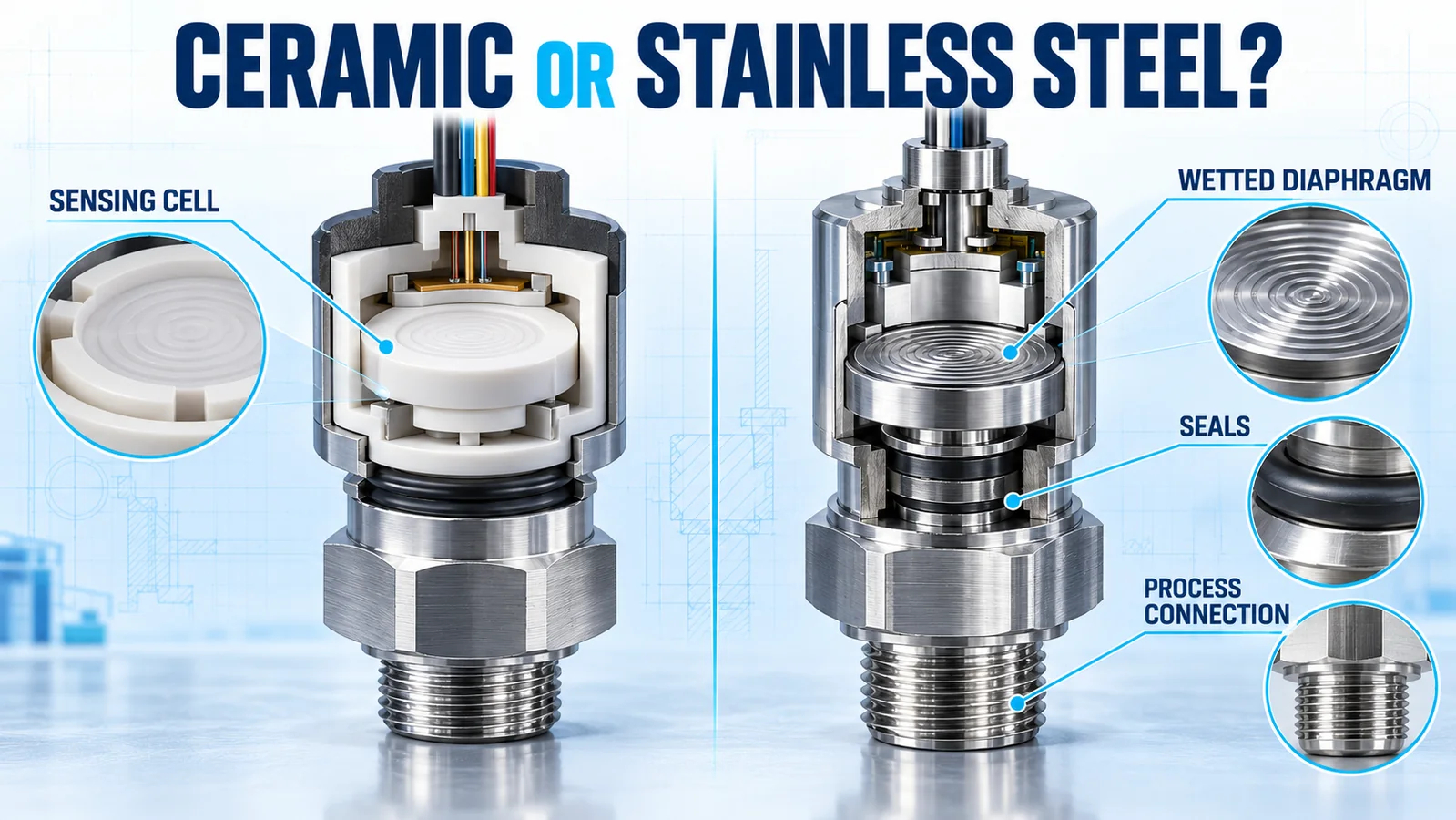
Comparing a ceramic vs stainless steel pressure sensor sounds like a choice between two construction materials. In practice, the labels often describe different layers of the sensing assembly. A ceramic sensor may place process pressure directly on a ceramic diaphragm while using a stainless steel housing and an elastomer seal. A stainless steel pressure core may use a thin 316L isolation diaphragm to transfer pressure to a silicon sensing chip behind it.
The useful selection question is therefore not simply “ceramic or stainless steel?” It is: which materials touch the medium, how does pressure reach the sensing structure, and which package can meet the chemical, mechanical, thermal and production requirements?
| Selection question | Ceramic piezoresistive cell | Stainless isolation-diaphragm core |
|---|---|---|
| Typical sensing path | Pressure acts directly on a ceramic diaphragm | Pressure acts on a metal diaphragm and is transferred to a silicon chip |
| Fill fluid | Usually absent in a direct dry cell | Common in an isolated silicon architecture |
| Seal dependency | Often uses an O-ring or gasket in the final assembly | Welded metal construction may reduce internal seal paths; installation seals can remain |
| Output at core level | Low-level bridge signal is common | Low-level normalized bridge signal is common |
| Key review | Ceramic grade, seal, port and mounting method | Exact metal grade, welds, fill fluid, port and isolation diaphragm |
| Best choice | Determined by the complete application | Determined by the complete application |
What Is the Short Answer?
Choose a ceramic piezoresistive cell when its direct, fill-fluid-free measurement architecture fits the medium and your package can control the seal, support and mounting stress. Choose a stainless steel isolation-diaphragm core when a welded metal pressure interface, compact OEM package or isolation of the silicon chip provides a better fit.
Neither description proves compatibility by itself. “Ceramic” does not identify the O-ring, port or housing. “Stainless steel” does not identify the grade, heat treatment, weld quality or any elastomer exposed at installation. The final decision must use the complete wetted-material list and the supplier’s conditions of use.
This article compares two common OEM architectures rather than every possible ceramic or metal pressure technology. The ceramic examples are piezoresistive thick-film cells. The stainless example is an isolated diffused-silicon core. For a broader starting point, use the industrial pressure sensor selection guide.
Why Is “Ceramic vs Stainless Steel” Not One Comparison?
A pressure sensor contains several functional layers. Marketing descriptions may name the sensing diaphragm, the isolation diaphragm, the pressure port or the external housing. Two products carrying different material labels may share some of the same materials, while two products both called stainless steel sensors may use different grades and internal technologies.
Sensing material and wetted material answer different questions
The sensing material is the structure whose deformation creates an electrical change. Wetted materials are every part exposed to the process medium. A ceramic diaphragm can be both sensing and wetted. In an oil-filled isolated core, the stainless diaphragm is wetted while the silicon chip senses pressure behind the isolation boundary.
Housing material is not enough
A stainless steel body can hold a ceramic cell. The medium may still contact ceramic, an elastomer and the port. Conversely, a silicon sensing chip can sit inside an all-stainless pressure package without touching the medium. A purchasing specification that states only “stainless steel sensor” leaves the actual exposure path undefined.
Which Material Layers Must Be Mapped?
Before evaluating a datasheet, draw the route from the process medium to the sensing structure. The WIKA overview of wetted parts defines the concept broadly: every part that contacts the medium belongs in the compatibility review.
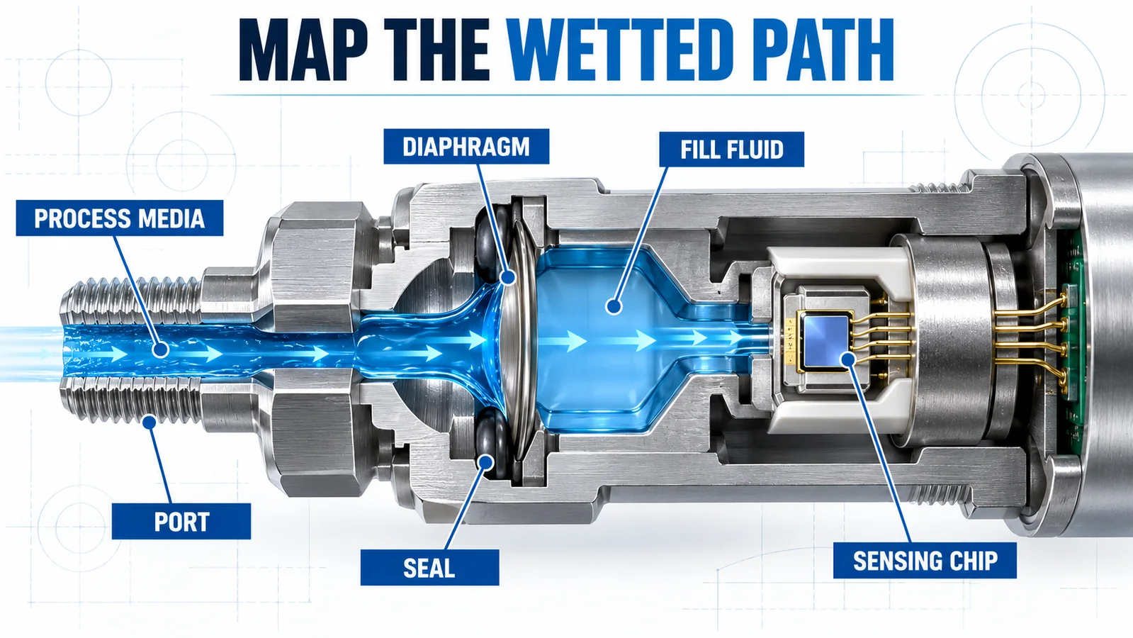
Process port and pressure connection
The port guides pressure into the sensor and carries installation torque. Its material, thread, surface finish and sealing method affect compatibility and mechanical reliability. A metal housing does not prove that the complete port uses the same alloy or receives the same surface treatment.
Diaphragm or exposed cell
Identify whether the medium reaches a ceramic cell directly or first meets a metal isolation diaphragm. Ask for the actual material designation. “Stainless steel” covers multiple alloys with different corrosion and strength behavior.
Seals, adhesives and fill fluid
O-rings, gaskets, bonding materials and potting may create the practical limit even when the main diaphragm is compatible. An isolated silicon core may also contain transfer fluid behind the diaphragm. Record whether a leak or diaphragm rupture could expose that fluid to the process.
How Does a Ceramic Piezoresistive Pressure Cell Work?
A ceramic piezoresistive cell uses a ceramic substrate and diaphragm with thick-film resistive elements arranged as a bridge. Pressure deflects the diaphragm, changes resistance and produces a differential millivolt signal. This is a different architecture from a ceramic capacitive sensor, even though both may use alumina ceramic.

Direct pressure and a dry sensing cavity
In a direct ceramic cell, pressure can act on the ceramic diaphragm without a metal isolation membrane or transfer liquid between the medium and the sensing structure. This removes one fluid-filled interface from the measurement path. The final assembly may still need a seal around the cell, so “dry cell” must not be read as “seal-free sensor.”
Low-level output needs OEM electronics
Ceramic cells such as Winsen WPAH01 and WPAH31 provide a bridge-level millivolt output. The OEM normally supplies stable excitation, amplification, compensation, calibration, electrical protection and the final connector or transmitter output. Material selection cannot be separated from the electronics and manufacturing plan.
Mounting method affects performance
The cell needs controlled support and compression. Uneven clamping, an unsuitable O-ring groove, housing distortion or thermal expansion can apply parasitic stress to the diaphragm. Prototype performance should be rechecked after the cell is installed in the production housing.
How Does a Stainless Isolation-Diaphragm Core Work?
In an isolated diffused-silicon core, process pressure deflects a thin metal diaphragm. A transfer medium carries that pressure to a silicon sensing chip inside the package. The metal diaphragm and package isolate the chip from direct process contact.

The metal is the process barrier
The isolation diaphragm is a functional part, not just an enclosure. Its alloy, thickness, welds and geometry influence corrosion resistance, overload behavior, temperature response and sensitivity. A 316L diaphragm is common, but the specification should name the actual grade for all relevant wetted parts.
Silicon provides the electrical sensing function
Calling the assembly a stainless steel sensor should not imply that stainless steel creates the piezoresistive signal. The silicon chip performs the sensing conversion while the metal diaphragm provides the wetted barrier. This distinction helps engineers compare architectures without confusing package material and sensing mechanism.
Isolation adds components to the error model
Diaphragm stiffness, transfer-fluid behavior and thermal expansion contribute to the complete response. These effects can be well controlled in a designed and compensated core, but they still belong in the validation plan. Compare supplier specifications at the same pressure range, temperature band and accuracy definition.
How Should Media Compatibility Be Evaluated?
Compatibility is a system property. A material may perform well with a medium at room temperature and fail at a higher concentration, a cleaning temperature or after repeated exposure. Request written compatibility guidance for the actual conditions rather than relying on a generic chart alone.
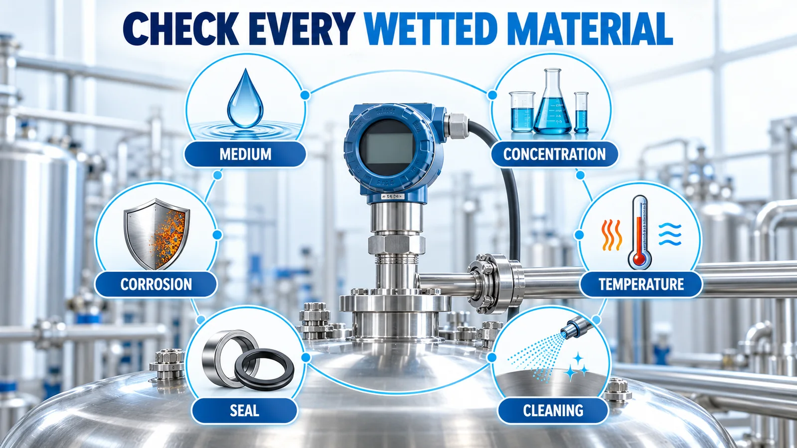
Define the medium precisely
Provide the chemical name, concentration, temperature range, pressure, exposure time, impurities and phase. For food, water-treatment or process equipment, include cleaning and sanitizing chemicals. For hydraulic service, include additives and possible contamination rather than specifying only “oil.”
Check every exposed component
Review the diaphragm or ceramic cell, port, seal, weld, coating and installation gasket. According to the TE pressure-transducer FAQ, material choice also depends on sensing technology; different stainless alloys cannot be treated as interchangeable.
Separate corrosion from other failure modes
Chemical attack is only one risk. Swelling, extraction, permeation, stress corrosion, galvanic interaction, particle erosion and deposit buildup can produce different failures. The correct material choice may require a sample test or a specialist review when process conditions are severe or uncertain.
What Role Do Seals, Welds and Leak Paths Play?
Sealing architecture can decide the practical difference between two sensors. A ceramic cell is commonly sealed into a housing with an elastomer. A stainless isolated core may use welded internal construction while the final process connection still needs a gasket, thread sealant or O-ring.
Elastomer choice is part of material selection
Specify the compound, hardness, temperature range, compression and chemical exposure. Names such as FKM or EPDM describe material families, not automatic approval for every formulation and medium. Compression set and assembly tolerances also affect long-term sealing.
Welded construction changes the risk profile
A welded metal isolation assembly can eliminate some internal elastomer joints. It introduces weld quality, heat-affected zones, thin-diaphragm integrity and manufacturing traceability as control points. Ask how leak testing and pressure testing are performed for the supplied core.
Installation creates additional boundaries
The sensor-to-process interface remains the machine builder’s responsibility. Thread engagement, torque, sealing face condition and fitting material can create leaks or stress even when the sensor core is correctly designed.
How Do Pressure Range and Mechanical Loads Affect the Choice?
Nominal pressure is only the starting value. Record maximum operating pressure, proof pressure, burst requirement, vacuum exposure, pulsation frequency and transient peaks. A material comparison without the package geometry and stated overload rating is incomplete.
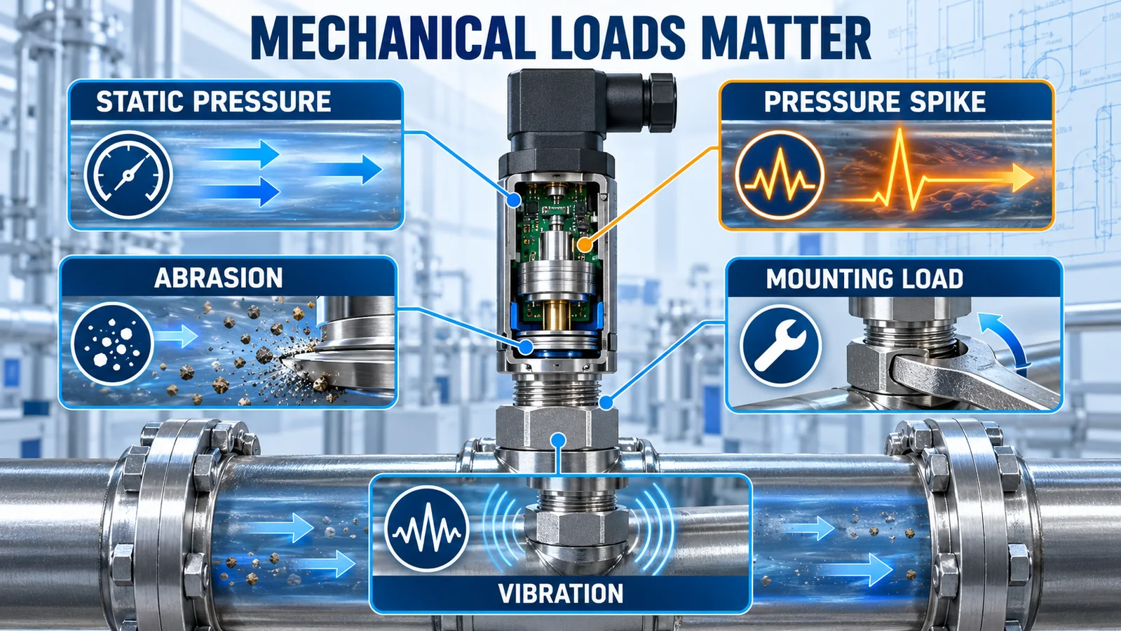
Pressure spikes and pulsation
Fast valve closure, pump ripple and hydraulic switching can create peaks that a slow control system does not display. Use sufficiently fast measurement during application testing or calculate the likely transient. A restrictor, snubber or changed mounting location may be necessary regardless of sensor material.
Abrasion and particles
Suspended particles can erode a thin isolation diaphragm or accumulate in a small port. A ceramic surface may resist some wear mechanisms, but the seal and port remain exposed. Review particle size, velocity, cleaning method and orientation rather than assuming one material solves the complete problem.
Mounting load and vibration
Torque and pipe strain can distort the housing. Vibration can fatigue wires, welds and connectors. Validate the assembled system at the actual mounting point, including cable support and thermal cycling.
What About Temperature, Drift and Long-Term Stability?
Temperature changes the elastic properties of diaphragms, bridge resistance, seal behavior, transfer fluid and the surrounding electronics. Datasheet temperature figures can describe operating, compensated, storage or media temperature; these are not interchangeable.
Compare specifications on the same basis
Check whether accuracy includes nonlinearity, hysteresis, repeatability, zero error and temperature effects. A smaller room-temperature linearity number may not deliver a smaller total error across the application range. The guide to pressure sensor accuracy, full scale and reading explains why the error model must be normalized before comparison.
Validate the installed package
Ceramic-to-metal expansion, O-ring compression and mounting stress can shift a direct cell. In an isolated core, diaphragm and transfer-fluid behavior can change with temperature. Test representative assemblies after thermal soak and cycling, not only loose sensing elements on a bench.
How Do Cleanliness and Fill Fluid Change the Decision?
A direct ceramic cell can avoid internal transfer fluid. That can simplify risk analysis where process contamination from a damaged isolation system is a concern. It does not automatically make the complete sensor hygienic or suitable for clean service.
Cleanability depends on geometry and materials
Crevices, dead volume, surface finish, exposed seals and process-connection geometry determine whether residue can be removed. A flush diaphragm may be more suitable than a recessed port for some viscous or sanitary processes, independent of whether the sensing technology is ceramic or silicon.
Isolation fluid requires an application review
For a filled core, ask what transfer fluid is used, the permitted temperature range and the consequence of diaphragm damage. Applications with special purity, oxygen service, food contact or regulated process requirements need documented approval from the component supplier and system owner.
What Changes for OEM Integration and Production?
Both architectures can be supplied as OEM sensing elements, so the buyer may own significant engineering work. The core versus complete transmitter comparison explains this responsibility boundary in detail.
Mechanical package and environmental protection
Define cell support, seal compression, port geometry, housing material, venting for gauge pressure, moisture barriers and connector protection. Do tolerance analysis before freezing the tooling. A change in seal supplier or machining process may require revalidation.
Calibration and compensation
Raw bridge output normally needs pressure and temperature calibration. Define reference equipment, calibration points, coefficient storage, traceability, acceptance limits and rework rules. Confirm whether supplier specifications apply to an uncalibrated cell, a compensated core or a complete calibrated assembly.
Service and change control
Record the exact material and revision in the bill of materials. Supplier changes to diaphragm thickness, ceramic formulation, seal compound or transfer fluid may affect performance or compatibility. Include notification requirements in the quality agreement for long-life programs.
Which Architecture Fits Common Applications?
The table below is a screening tool, not an approval chart. Final selection requires the supplier datasheet and application validation.
| Application condition | First architecture to investigate | Questions that can change the answer |
|---|---|---|
| General water or pump pressure | Ceramic cell or stainless isolated core | Water chemistry, seal, freeze risk, transients and package cost |
| Hydraulic machinery | Stainless isolated core is often a practical starting point | Peak pressure, pulsation, port size, fatigue and fluid additives |
| Corrosive chemical | No default; perform full material review | Exact chemical, concentration, temperature, all wetted parts and special alloys |
| High-volume OEM appliance | Ceramic cell can offer packaging flexibility | Calibration capability, seal design, production yield and service model |
| Vacuum or compound range | Verify a purpose-designed core | Reference type, overpressure direction, fill-fluid behavior and venting |
| Clean or hygienic process | Purpose-designed flush or hygienic assembly | Surface finish, crevices, cleaning method, approvals and contamination limits |
| Abrasive slurry | Special material and geometry review | Particle velocity, diaphragm thickness, flush mounting and maintenance interval |
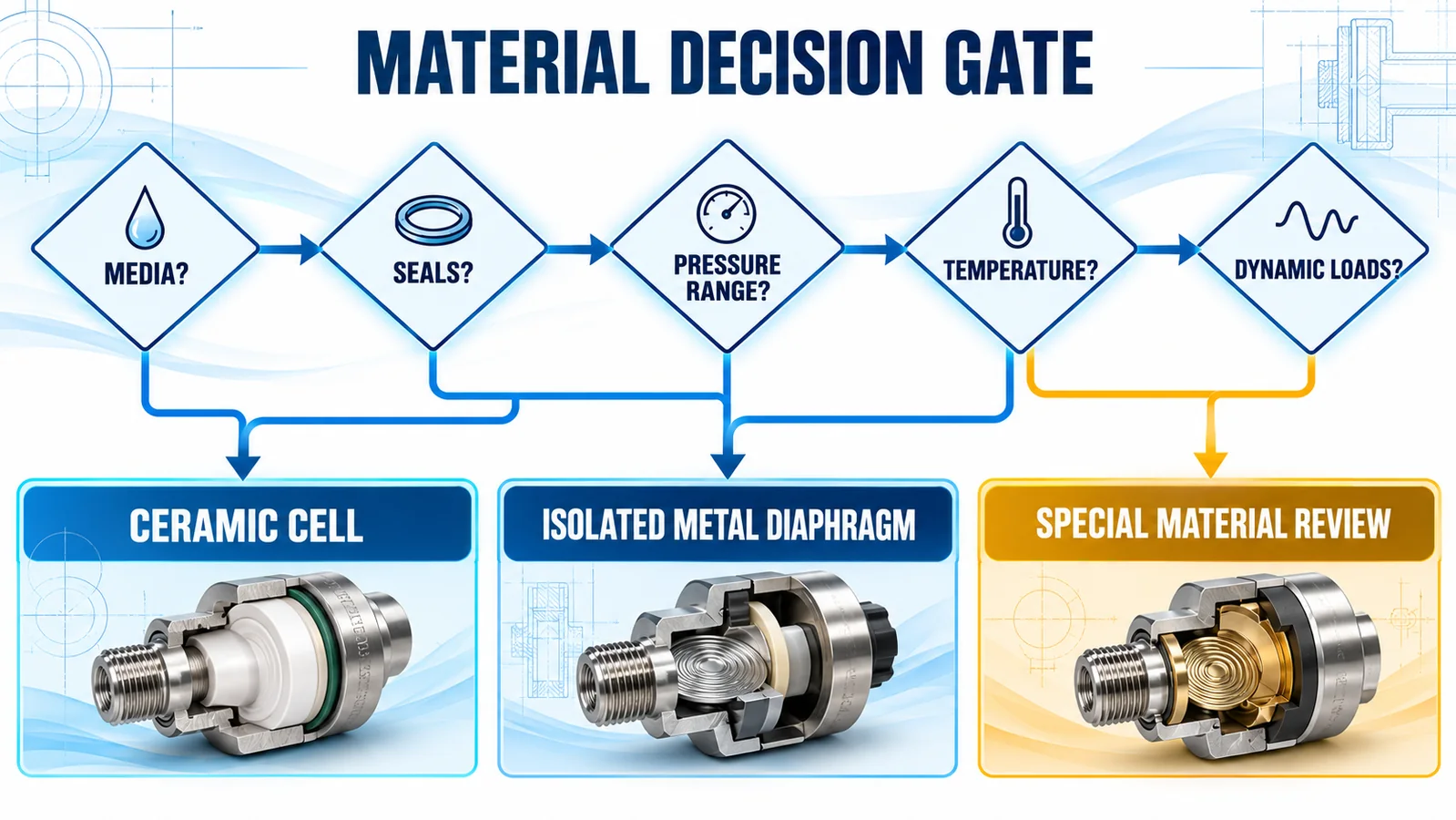
If any wetted material is uncertain, stop at “special material review.” Changing only the housing to stainless steel does not resolve an incompatible seal or diaphragm.
How Do Winsen WPAH01, WPAH31 and WPAK63 Differ?
Winsen offers examples of both architecture families. Use the current official datasheet and engineering confirmation for the chosen range and configuration before design release.
| Modello | Architecture | Pressure interface | Published range and temperature | OEM implication |
|---|---|---|---|---|
| WPAH01 | Ceramic piezoresistive thick-film cell | Ceramic sensitive diaphragm; final housing and seal are OEM-defined | 2–400 bar; -40 to 125°C | Compact 18 × 6.35 mm cell with millivolt bridge output; OEM handles packaging, compensation and calibration |
| WPAH31 | Ceramic piezoresistive thick-film cell | Ceramic sensitive diaphragm; final housing and seal are OEM-defined | 2–400 bar; -40 to 125°C | Similar 18 × 6.35 mm integration class; confirm the exact electrical and performance option |
| WPAK63 | Isolated diffused-silicon pressure core | 316L stainless steel housing and diaphragm | Multiple gauge, absolute and sealed-gauge ranges; use the current manual | 19 mm OEM core with normalized bridge output; integrate excitation, compensation, package and final calibration |
WPAH01 and WPAH31 should not be described as ceramic capacitive devices. Their published principle is ceramic piezoresistive. WPAK63 should not be described as a solid stainless sensing element: its 316L diaphragm isolates the internal silicon sensing structure.
What Should an RFQ and Validation Plan Include?
A useful request for quotation gives the supplier enough detail to reject an unsuitable material combination before samples are built.
Application and media data
List pressure reference type, normal range, peak and vacuum conditions, medium composition, concentration, particles, operating temperature, cleaning chemicals, exposure duration and expected life. Add the installation orientation and process connection.
Performance and electrical data
Define supply or excitation, output, total error across temperature, response time, overload, EMC environment and diagnostics. State how accuracy will be calculated and which errors are included.
Production and quality data
Ask for the complete wetted-material list, seal designation, diaphragm alloy, fill fluid where applicable, traceability, change-control process and test evidence. Plan incoming inspection, calibration, leak testing and validation of the finished assembly.
Domande frequenti
Is ceramic always more corrosion resistant than stainless steel?
No. Compatibility depends on the ceramic composition, stainless alloy, seals, other wetted parts and the exact chemical conditions. Review the full exposure system.
Does a ceramic pressure sensor contain no stainless steel?
Not necessarily. A ceramic sensing cell can be installed in a stainless steel port or housing. The material name must be tied to a specific component.
Does a stainless steel pressure sensor contain no ceramic or silicon?
Not necessarily. A stainless steel isolation diaphragm commonly protects an internal silicon chip. Other designs can combine a ceramic cell with a metal body.
Which architecture is better for pressure spikes?
Use the specified proof pressure, burst pressure, fatigue behavior and application transient data for the complete package. Material name alone cannot determine spike survival.
Can the same calibration process be used for both?
The equipment may be shared, but compensation models, mounting stress, thermal behavior and acceptance limits can differ. Calibrate and validate the production assembly using the supplier’s recommended excitation and conditions.
Build the Material Decision from the Medium Outward
A reliable ceramic vs stainless steel pressure sensor decision starts at the process medium and moves outward through the diaphragm, seal, port, housing and electronics. Separate the material exposed to the medium from the material that produces the electrical signal. Then compare pressure dynamics, temperature, cleanliness, packaging, calibration and lifecycle control.
Winsen’s ceramic piezoresistive WPAH01 and WPAH31 cells and 316L-isolated WPAK63 core represent different integration paths. The best fit depends on the complete application and the engineering work the OEM is prepared to own. For a material review or an OEM selection checklist, contact Winsen engineers with your medium, range, temperature, output and mechanical requirements.
