

A duct static pressure sensor is only as useful as its pickup location and pressure reference. For a variable-air-volume (VAV) supply system, choose a duct section that represents the pressure available to the terminals, then install a static pickup in a locally straight, low-turbulence portion of that section. Connect the pickup and the intended reference to the correct sides of a suitably ranged pressure sensor. Finally, compare the installed reading with a calibrated field instrument while the fan and terminal demand change.
That is the short answer. Four decisions make it work in practice:
- Define the measurement: supply duct relative to which space or pressure reference? A filter pressure drop and a room-to-corridor pressure difference are different measurements.
- Choose two locations: the representative point for the control loop and the clean local surface where a static tap can actually sense it.
- Match the instrument: expected minimum, normal and maximum pressures; polarity, accuracy basis, overload limit, medium, output and installation environment.
- Commission the whole signal path: tap, tubing, reference, sensor, controller scaling and fan response.
What does a duct static pressure sensor measure?
Static pressure is the pressure the moving air exerts on the duct wall, expressed relative to a stated reference. In a typical positive-pressure supply duct, a differential instrument can report duct static pressure − reference-space pressure in pascals (Pa) or inches of water column (in. w.c.). It is not automatically an absolute pressure reading. Our pressure-types guide explains the difference between gauge, absolute and differential references.
Air motion adds velocity pressure. The sum of static and velocity pressure is total pressure, as described in the ASHRAE Duct Design chapter. A pickup that faces directly into an air stream can receive impact pressure and make a static reading too high. A plain sidewall static tap has a smooth, burr-free opening normal to the airflow; an engineered static probe may instead use side-facing openings. The DwyerOmega measurement guide distinguishes those geometries and notes that turbulence can still affect a wall tap.

Do not interchange three HVAC measurements merely because each uses a differential sensor. Supply-duct static pressure compares one duct location with a defined reference. Filter pressure drop compares taps upstream and downstream of the filter. Room pressure compares a controlled room with an adjacent room or other specified space. Each requires different pickup placement and high/low plumbing.
Where should a duct static pressure pickup go?
First choose a representative control location
For a VAV system, the supply-fan controller needs a pressure signal that reflects terminal demand. A pickup immediately at the fan discharge may show pressure the fan creates while telling the controller too little about pressure available farther down the network. At the opposite extreme, placing a sensor at one remote terminal can make the loop disproportionately sensitive to that terminal. ASHRAE’s controls guidance discusses both problems and pressure-setpoint reset using VAV terminal data.
Therefore, do not use a generic “two-thirds down the duct” rule without examining the actual branches, critical terminals, control sequence and commissioning results. Select the control region with the designer or balancing team. If the system uses multiple branches or a static-pressure reset sequence, document which sensor controls the fan and how critical-zone data changes the setpoint. A pressure transducer cannot repair a poor control point by having a finer digital resolution.
Then find a clean spot for the actual tap
Within the chosen region, look for a straight, accessible duct section with stable airflow. Avoid the wake of elbows, takeoffs, transitions, dampers, turning vanes and the fan. The ASHRAE Duct Design chapter recommends placing in-duct static sensors in low-turbulence sections at least three equivalent duct diameters from such disturbances. A particular equipment or probe manual may call for a different or longer distance; follow the applicable design and hardware instructions. For example, a Johnson Controls system note specifies its own stable-plenum placement rules.

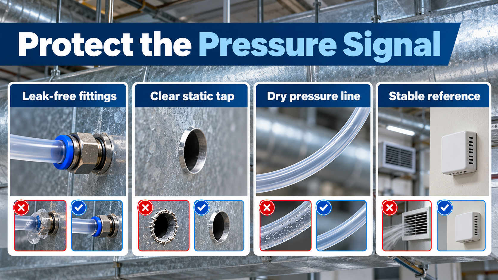
For a simple flush wall tap, make the opening clean and flush with the inside wall. Do not let an improvised tube project into the flow or point upstream. A purpose-made probe has its own airflow-arrow or orientation instructions, so install it as its maker specifies. Keep the location accessible for inspection and a field comparison. Record the exact branch, distance from recognizable fittings and tap orientation on the commissioning drawing.
How should the high and low pressure sides be connected?
A two-port differential sensor reports high-side pressure minus low-side pressure. For a positive-pressure supply duct measured relative to a stable reference space, connect the duct static tap to HIGH (+) and the reference to LOW (−). The resulting positive number has a clear meaning only if the reference location is written down. A Johnson Controls duct installation instruction explicitly routes a high-side tube to the supply-duct static tap.

For a negative-pressure return or exhaust duct, the sign reverses if the same high/low convention is kept. You can change plumbing or controller sign conventions where the approved device and controls design allow, but label the result and verify the alarm logic. Never swap ports simply to make a display positive without documenting the measurement definition. An open low port also does not mean “outdoor atmosphere” if the transducer sits in a pressurized AHU cabinet or a room with variable pressure. Route the low side to the intended stable reference, and protect its opening from local drafts.
Use tubing and fittings compatible with the pressure, temperature and air conditions. Check every joint for leakage and the tap for obstruction. Route and maintain the line so liquid cannot accumulate at or enter a device that is not rated for it; follow the probe and sensor instructions for condensation handling. Keep the reference pickup away from fan discharge, air outlets, frequently opened doors and other changing pressure zones. A blocked tube, leaky fitting or wet line can produce a convincing but false control signal. The PNNL guide to functional static-pressure reset lists loose or plugged sensing lines and poor sensor location among practical diagnostic causes.
How do you choose the sensor range?
Start with the system’s actual design and balancing data. Record the lowest expected pressure, the ordinary control band, and the highest pressure that can occur during startup, damper changes or a credible fault. Choose a measuring range that includes the specified operating conditions with appropriate margin. Separately check maximum differential and common-mode/overpressure ratings; the upper measurement endpoint is not automatically a safe overload limit.
For illustration only, suppose a positive supply duct normally varies around 250 Pa, could reach 500 Pa during intended operation, and a design review concludes a 0–1000 Pa measuring range is appropriate. Those numbers describe a hypothetical system, not a recommended setpoint or a Winsen order code. A 0–10 kPa range might cover it too, but it can make a full-scale-based error specification much less useful at 250 Pa. Conversely, an overly narrow range may clip startup or fault conditions. See our full-scale-versus-reading accuracy guide before comparing accuracy percentages.

| Selection item | Specify before ordering | Why it matters |
|---|---|---|
| Pressure quantity | Duct-to-reference static pressure; positive, negative or bidirectional | Determines port polarity and whether a unidirectional range suffices |
| Operating range | Minimum, normal band and maximum expected measurement | Prevents clipping or unnecessarily broad full scale |
| Accuracy basis | Error at the temperatures and pressures relevant to the control loop; %FS O %reading stated explicitly |
A data-sheet percentage alone does not establish error at a low operating point |
| Sovrapressione | Permitted pressure at each port and differential across the element | Must cover realistic fault and startup cases separately from measurement range |
| Medium and environment | Air quality, humidity/condensation, temperature, vibration and mounting protection | A bare sensor package is not a weatherproof duct transmitter |
| Interface | I²C at PCB level, or a field-ready analog/digital BAS interface as required | Must match the OEM electronics or building controller |
For unit conversion, 1 in. w.c. (conventional) is about 249 Pa. State the water-column convention when precision matters, and keep the BAS scaling in the same units as the device. Our pressure-units guide has a broader conversion table.
How do you commission and troubleshoot the reading?
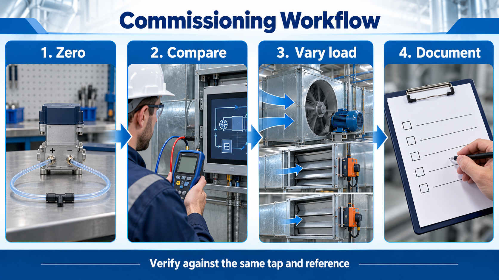
An attractive dashboard value is not proof that the duct pressure is being sensed correctly. Follow the instrument maker’s zero procedure, then compare the installed signal with a calibrated portable manometer using the same duct tap and reference point wherever the installation allows. Check the controller’s engineering-unit scaling and polarity. Repeat observations at several normal fan-speed and VAV-load states; a single no-load reading cannot reveal every placement or tubing problem.
| Sintomo | First checks | Possible system issue after sensor path is verified |
|---|---|---|
| Reading near zero or lower than expected | Wrong reference, loose/disconnected tube, plugged tap, reversed polarity, zero/scaling | Fan override, duct leak, closed damper or insufficient airflow |
| Reading jumps or hunts | Tap too close to turbulent fitting, draft at reference, wet/partly blocked tube, unsuitable filtering | Unstable fan-control loop or rapidly changing VAV demand |
| Reading high near fan but zones lack air | Sensor at a nonrepresentative near-fan point; compare farther along the system | Restrictions or poor distribution to critical terminal |
| BAS value disagrees with field manometer | Use identical tap/reference, verify units and calibration, check tubing leak | Then examine control system input and signal conversion |
These are diagnostic possibilities, not a replacement for test-and-balance work. ASHRAE controls guidance emphasizes the role of sensor location in stable, efficient control, while the PNNL troubleshooting guide gives field examples of failed or poorly located sensors. Keep the final record of tap location, reference point, tubing route, range, zero method, field readings and control sequence.
Where does Winsen WPAS13 fit?
IL official Winsen WPAS13 page identifies WPAS13 as a board-level digital micro differential-pressure gas sensor, with dual nozzles, a MEMS piezoresistive core and I²C output. Its published family range list includes −0.5 to +0.5 kPa (−500 to +500 Pa) and wider options, plus optional unidirectional ranges beginning at 0–0.5 kPa. The page lists ±1% FS accuracy and a −5 to 65°C working-temperature range. The specific orderable variant and its port ratings must be confirmed before selection.
WPAS13 can be considered as an OEM sensing component when the equipment designer supplies the static pickup, appropriate pneumatic tubing, enclosure/PCB integration, power and I²C electronics, moisture protection, calibration and BAS-facing output. It is non a finished wall-mounted or duct-mounted pressure transmitter, and the official page does not establish that it can be placed directly in a wet duct or wired straight to a standard BAS analog input. Ask Winsen for the current variant data sheet, proof/overpressure data, clean-air compatibility limits and integration guidance for the intended environment. Our industrial sensor selection guide covers the other purchasing dimensions.
What to include in an OEM or project RFQ
Send the duct layout and control sequence along with the specified duct tap location and reference, expected minimum/normal/maximum differential pressure, possible overpressure, temperature and humidity, condensation risk, signal update needs, supply voltage and controller interface. State whether you need a PCB-level differential element or a complete field transmitter. For WPAS13, request the exact range variant, pressure-port and mounting data, environmental limits, calibration/accuracy conditions and a sample integration schematic. Contact Winsen’s team with those requirements so the proposed part can be checked against the actual HVAC application.
Domande frequenti
Is a duct static pressure sensor the same as an airflow sensor?
No. It measures pressure relative to a reference. Airflow measurement normally requires a device and method designed to infer or measure velocity/flow. Pressure can support fan control, but a single static reading does not by itself establish duct airflow.
Should the duct static tap face into the airflow?
No for a plain wall static tap: its opening should be perpendicular to the flow and flush/smooth inside the duct. A manufacturer-designed static probe can project into the duct but must be oriented according to its specific instructions. A forward-facing impact opening measures total/impact effects rather than clean static pressure.
Where is the best VAV duct static pressure sensor location?
There is no universal point for every network. Choose a location representing terminal demand, then use a locally low-turbulence straight section for the pickup. Avoid making the fan-discharge pressure or one unrepresentative terminal drive the whole system; verify the final location during balancing and controls commissioning.
Which side of a differential sensor connects to a positive supply duct?
Connect the positive supply-duct static tap to HIGH (+) and the selected reference to LOW (−) if the desired reading is duct minus reference. Record that reference and verify device and controller polarity.
What pressure range should I specify?
Use project design and measured data, including operating extremes and faults. A range such as 0–1000 Pa can be a useful illustrative comparison, but it is not a universal recommendation. Evaluate error at the actual operating point, overload separately, and whether the required signal interface is PCB-level or field-ready.
Why does the reading change after the tube is connected?
The tube may connect to a different pressure reference, leak, contain condensate or terminate at a turbulent tap. Check the complete path and compare a calibrated manometer at the same tap and reference before changing the fan setpoint.
