

A natural gas pipeline pressure sensor is most useful when its location answers a defined operating question. Pressure transmitters at a station inlet and outlet can show regulator performance. Devices at compressor suction and discharge can show compression conditions. Sensors at branch junctions and network extremities can reveal whether pressure reaches critical downstream users. The value comes from the relationship between measurements, not from installing one transmitter and treating it as a complete safety system.
Pressure monitoring supports control, trending and alarms. It does not replace pressure regulators, monitor regulators, slam-shut valves, relief devices, combustible-gas detectors or a validated leak-detection method. A pressure drop may result from higher demand, valve movement, compressor shutdown, regulator behavior, instrument error or a leak. Operators need the wider process context before assigning a cause.
| Monitoring question | Useful measurement locations |
|---|---|
| Is supply pressure available? | Source or station inlet |
| Is compression performing normally? | Compressor suction and discharge |
| Is regulation stable? | Regulator inlet and outlet, with the correct sensing taps |
| Is a branch receiving adequate pressure? | Branch takeoff and downstream critical point |
| Is the network pressure profile changing? | Major nodes, sectionalizing points and extremities |
| Does a meter have compensation data? | At the pressure reference defined for the flow calculation |
| Is a filter becoming restricted? | Upstream and downstream pressure, or a suitable differential measurement |
What Can Pipeline Pressure Monitoring Tell You?
Pressure data shows how the gas network responds to supply, demand, resistance and control actions. A single reading is a condition at one point and time. A group of synchronized readings can show gradients across a pipe segment, pressure reduction across a regulator, compression ratio, line-pack changes and whether a low-pressure area is developing.
Operating visibility and alarms
Continuous telemetry can support high, high-high, low, low-low and rate-of-change alarms. Alarm settings must come from the operator’s approved pressure limits, hydraulic analysis, equipment ratings and response procedures. A normal operating band is not the same as the maximum allowable operating pressure, and an alarm is not the protective device that limits pressure.
Pressure trends support diagnosis
A sudden change at several adjacent points may indicate a supply or control event. A gradual loss of margin at an extremity may indicate growing demand, restriction or changed network conditions. Comparing inlet and outlet trends at a regulator can help identify hunting, lock-up concerns or inadequate capacity. These are diagnostic clues that require confirmation.
Pressure is not direct gas detection
A pressure transmitter measures pressure at its connection. It does not measure methane concentration around a pipe. Small leaks may not create a unique pressure signature, while large demand changes can create significant pressure drops without a leak. Leak management can require flow balance, computational monitoring, acoustic methods, odorant reports, patrols and fixed or portable combustible-gas detectors. Pressure data can contribute, but it cannot prove leak presence or location by itself.

Where Should Sensors Be Placed in the Network?
Start with a simplified network model: source, compression, pressure-reduction stations, major branches, storage or line-pack sections, metering points and critical users. For each proposed instrument, write the decision its data will support. This prevents redundant points and exposes blind spots.

Measure both sides of major energy changes
Install independent measurements upstream and downstream of compressors and major regulators when the operating objective requires differential behavior. A downstream-only reading cannot show whether low pressure originated from inadequate inlet supply or from the equipment between the points.
Cover hydraulic boundaries and extremities
Major branch takeoffs, interconnections, sectionalizing valves and terminal points define how pressure propagates through the network. Critical low-pressure points are often near network extremities or high-demand zones. Their measurements can validate hydraulic models and confirm service margin during peak demand.
Add temporary survey points when needed
Permanent monitoring should cover control and critical locations. Portable or temporary pressure recorders can fill gaps during seasonal peaks, commissioning or model validation. Temporary data still needs synchronized time, documented tap location, calibrated instruments and controlled retrieval.
How Should City-Gate and Compressor Stations Be Instrumented?
A city-gate or custody-transfer station links networks with different operating conditions. Typical pressure points include the station inlet, downstream of filtration where relevant, regulator inlet and outlet, meter pressure reference, and station outlet. The exact arrangement depends on the station process diagram and applicable standards.
Compressor suction and discharge
Suction pressure protects operating margin and helps explain reduced capacity. Discharge pressure shows delivered condition and contributes to control and alarm logic. Where pulsation is present, the measurement assembly may need a suitable tap, damping arrangement or signal filtering that preserves the transients the control system must see.
Station inlet and outlet
These values establish the available pressure drop and confirm what the station receives and delivers. If filtration, heating, metering and regulation are combined, intermediate points can help locate restriction or abnormal loss. Avoid adding taps without evaluating integrity, isolation and maintenance access.
Where Do Pressure Sensors Fit Around Regulators?
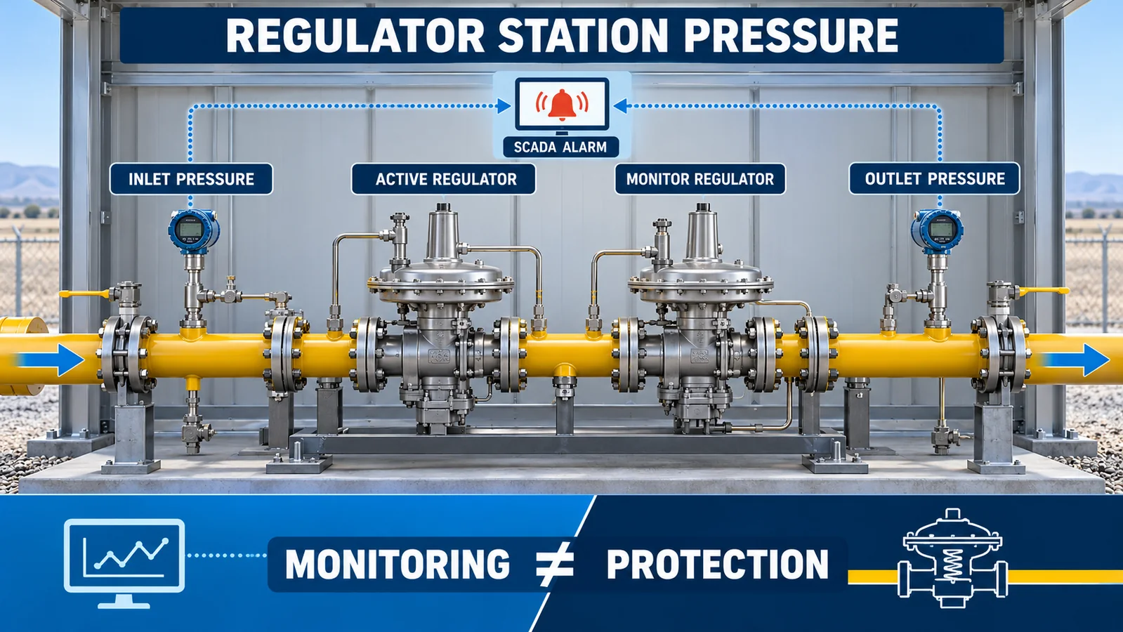
Regulator stations reduce pressure and require independent overpressure protection based on the approved design. Pressure monitoring makes performance visible to operators; it does not perform the mechanical protective function unless it is part of a separately engineered and validated safety instrumented function.
Inlet pressure
The inlet transmitter shows whether sufficient upstream pressure is available and whether the regulator is operating within its intended differential. It also helps distinguish upstream supply loss from a station problem.
Outlet pressure
The outlet point is central to control verification and high- or low-pressure alarms. Place the measurement where it represents the controlled downstream system and follows the regulator manufacturer’s rules for sensing-line taps, straight lengths, turbulence and distance from fittings.
Monitor regulators and relief devices
Series monitor regulators, slam-shut devices and relief valves have their own sensing and setpoint requirements. A SCADA transmitter can provide independent visibility, but shared taps, plugged impulse lines or common power and wiring can create common-cause failures. The protective design and the monitoring design should be reviewed together while retaining the required independence.
Which Distribution and Terminal Points Matter Most?
Distribution systems can have multiple pressure tiers. The correct sensor range and alarm logic for a medium-pressure feeder may be unsuitable for a low-pressure utilization network. Document the pressure tier and reference at every tag.
Branch junctions and district feeds
Measurements before and after a major branch help show how demand is divided. A sensor at the branch inlet can confirm supply, while a downstream critical point shows what customers actually receive. Interconnected districts may require points on both feeds to identify changing flow direction or imbalance.
End-of-line and critical customers
Network extremities can lose margin first during peak demand or an upstream restriction. Hospitals, industrial processes or other critical users may justify dedicated telemetry, subject to the operator’s risk assessment and contractual boundary. Instrument ownership and maintenance responsibility must be clear.
Valve stations and crossings
Pressure measurements on selected sides of sectionalizing valves can confirm isolation, support recommissioning and help interpret a closed or partially closed valve. They should not be added indiscriminately; each penetration, enclosure and cable route needs an integrity and hazardous-area review.
How Do Metering and Filter Measurements Differ?
Pressure used for gas-volume compensation must represent the meter’s defined pressure condition. The tap location, pressure reference, units, time alignment and calculation basis must match the flow computer design. A convenient nearby tap is not automatically valid for custody or energy calculations.
Flow compensation
Gas volume changes with absolute pressure and temperature. If the calculation requires absolute pressure, using a gauge-pressure value without adding the correct atmospheric reference creates error. Confirm whether the transmitter provides gauge, absolute or sealed-gauge pressure and how the controller interprets it.
Filter and strainer condition
A restriction is evaluated from pressure loss across the element. Two gauge transmitters can be compared if their accuracy, ranges and time alignment support the expected differential. A dedicated differential-pressure measurement may be better for a small pressure drop on a high static pressure. The instrument choice should follow the required uncertainty and overpressure conditions.
How Do You Select Range, Reference and Output?
Selection begins with the actual pressure envelope at each node, including startup, shutdown, blocked-in conditions, regulator failure cases, compressor transients and testing. Choose a range with suitable margin while preserving the resolution needed for the operating band.

Match the pressure tier
Do not standardize every point on the highest available range. A 60 MPa transmitter used on a low-pressure distribution point can produce an unnecessarily large absolute error allowance when accuracy is stated as a percentage of full scale. At higher-pressure points, verify proof, overload and burst information for the exact selected range.
Choose the pressure reference deliberately
Gauge pressure is common for pipeline operation. Absolute pressure is often needed for gas-law and flow-compensation calculations. Sealed gauge can be appropriate at higher ranges where atmospheric variation is small relative to span. Record the reference in the tag database, drawings and controller configuration.
Confirm the complete signal chain
Check power supply, output, cable length, grounding, isolation, analog-to-digital conversion, sample rate and diagnostics. Low-voltage and I²C interfaces are normally integrated into nearby electronics; they are not automatically suitable for long field cable runs. A remote telemetry architecture may need a signal conditioner or transmitter assembly designed for the distance and environment.
What Installation Details Affect the Reading?
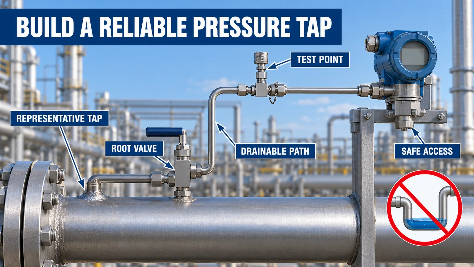
The pressure port must expose the diaphragm to a representative gas pressure while protecting system integrity. Installation errors can create slow response, trapped condensate, contamination, leakage paths or unsafe maintenance conditions.
Pressure tap and impulse path
Follow the project standard for tap orientation, root valve, tubing, manifold and test connection. Minimize dead volume and avoid pockets where liquids or debris can collect. If condensation is credible, define drainage, heat tracing or separation measures appropriate to the gas composition and climate.
Pulsation and vibration
Compressors, fast valves and regulators can create pulsation. Mechanical snubbers and digital filtering can stabilize a displayed value, but excessive damping can hide a real transient or delay an alarm. Set response requirements before selecting damping.
Isolation and maintainability
Provide a controlled way to isolate, depressurize, verify zero and connect a calibration standard. Valve position and trapped pressure must be addressed in the procedure. The instrument should be accessible without exposing personnel to an uncontrolled gas release.
What Must Be Verified for Hazardous Areas and Safety Functions?
Natural gas installations may be classified hazardous locations. Compliance belongs to the complete installed configuration: sensor or transmitter, enclosure, gland, cable, barrier, power source, grounding, ambient range and installation method.
Certification is configuration-specific
An enclosure described as explosion-proof does not automatically certify every device installed inside it. Likewise, a manufacturer’s general statement that different products can carry different approvals is not evidence for a particular model. Request the current certificate, marking, schedule and installation instructions covering the exact ordering code.
Monitoring and protection have different roles
SCADA pressure data helps operators detect and respond to abnormal conditions. Overpressure protection is provided by the engineered regulator, monitor regulator, slam-shut, relief or safety instrumented function required by the system design. Avoid a single transmitter, shared impulse line or common controller becoming an undocumented single point of failure.
Cybersecurity and data quality
Remote pressure data needs authenticated communication, time synchronization, controlled setpoint changes, audit logs and clear handling of stale or bad-quality values. A believable number with an old timestamp can be more dangerous than an obvious communications failure.
How Should Alarms, Commissioning and Maintenance Be Managed?
Alarm design should produce actionable information. Too many nuisance alarms train operators to ignore them, while a single broad limit can miss a rapid change or abnormal relationship between adjacent points.

Build alarms from operating scenarios
Define the condition, detection logic, delay, priority, operator action and escalation for each alarm. Consider high, high-high, low, low-low, rate-of-change, transmitter fault, stale data and disagreement between related points. Test alarms against startup, shutdown and peak-demand conditions.
Commission point to point
Verify tag, location, range, reference, units, scaling, polarity, timestamp, alarm setpoints and historian mapping. Apply known pressures at several points and confirm the value at the field device, local controller, SCADA display, alarm engine and historian. Record as-installed taps, valves, cable routes and enclosure details.
Maintain the measurement system
Inspection intervals should reflect drift history, cycling, environment and consequence of error. Check for corrosion, moisture ingress, damaged cables, blocked taps, leaking fittings and unauthorized configuration changes. Calibration alone will not find every installation fault.
How Do Winsen WPCK63 and WPCK68 Compare?
Both current Winsen pages describe compact diffused-silicon pressure transmitters for gas pressure measurement with stainless-steel construction, IP68 protection, ±0.5%FS accuracy and ≤1 ms response. Their published mechanical integration and maximum range differ.
| Published item | WPCK63 | WPCK68 |
|---|---|---|
| Pressure range family | -100 kPa to 6 MPa | -100 kPa to 60 MPa |
| Referencia de presión | Manómetro / absoluto / manómetro sellado | Manómetro / absoluto / manómetro sellado |
| Standard output | 00,2–2,3 V/I²C | 00,2–2,3 V/I²C |
| Exactitud | ± 0.5%FS | ± 0.5%FS |
| Tiempo de respuesta | ≤1ms | ≤1ms |
| Temperatura de trabajo | -30°C to 85°C | -30°C to 85°C |
| Standard thread | M20×1.5; others customizable | M20×1.5 / G1/2 |
| Conexión eléctrica | Corrugated-conduit cable with M12 aviation connector | XH2.54 terminal |
| Integration note | Compact field-style assembly | Published as suitable for installation inside a 2088 explosion-proof enclosure |
WPCK63 can be evaluated where its range, interface and mechanical form fit the monitoring assembly. WPCK68 extends the published range to 60 MPa and is described for enclosure integration. Neither product should be selected from maximum range alone. Confirm the exact range-specific overload, media compatibility, pressure port, output, power, cable or enclosure, environmental limits and current approvals.
What Should Be Included in the RFQ?
Provide a point list with:
- pipeline segment and monitoring purpose;
- normal, minimum, maximum and transient pressure;
- referencia de calibre, absoluta o de calibre sellado;
- gas composition, contaminants and possible condensate;
- ambient and process temperature;
- process connection, tap and isolation arrangement;
- required output, power, cable length and controller interface;
- sample rate, response and alarm use;
- hazardous-area classification and required certificate;
- enclosure, ingress, grounding and surge requirements;
- accuracy, drift and calibration expectations;
- quantity, documentation and traceability requirements.
Winsen can review WPCK63, WPCK68 or a customized configuration against this point list. Final suitability depends on the complete instrument assembly and the operator’s engineering and regulatory requirements.
Preguntas frecuentes
Can one pressure sensor monitor an entire gas pipeline?
No. One point cannot show pressure gradients, regulator differential or conditions at distant branches. Use a network of points selected from the hydraulic model and operating risks.
Can a pressure drop alarm confirm a gas leak?
No. It indicates an abnormal pressure condition that may have several causes. Leak confirmation and localization require the operator’s approved detection and investigation methods.
Should sensors be installed before and after every regulator?
Major and safety-relevant regulator stations commonly benefit from inlet and outlet visibility, but the exact instrumentation follows the station design, consequence assessment and applicable rules.
Is the highest available pressure range the safest choice?
No. Excessive range can reduce useful resolution and increase absolute error when accuracy is specified in %FS. Select range from the complete pressure envelope and required uncertainty.
Does IP68 mean the transmitter is explosion-proof?
No. IP ratings address ingress protection. Hazardous-area approval is a separate certification covering the exact device and installation conditions.
What is the next step?
Send Winsen the pressure-point list, gas composition, connection, output, environmental limits and hazardous-area requirements to request a configuration review and current data sheet.
