
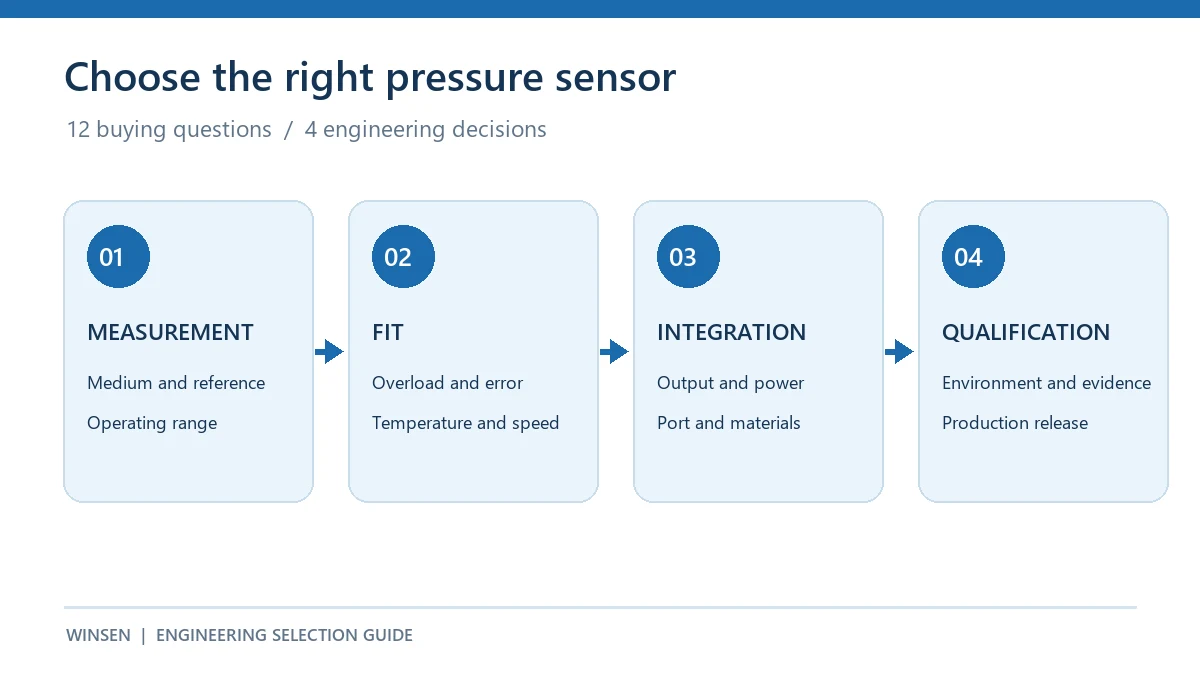
Choosing an industrial pressure sensor starts with a measurement specification, not a part number. Define the process medium and pressure reference, record the normal range and credible peaks, calculate the error your system can tolerate, and then match the electrical and mechanical interfaces. Before an OEM release, verify the exact ordered configuration with a data sheet, drawing, and samples.
This 12-question guide is for engineers and technical buyers who need a pressure device for pumps, hydraulic units, pneumatic equipment, water treatment skids, or other industrial machinery. “Pressure sensor” is used broadly here. A bare sensing core, a conditioned module, and a field transmitter can all measure pressure, but they leave different amounts of signal conditioning, protection, and calibration work to the equipment maker. If that distinction is central to your design, see our sensor vs. transducer vs. transmitter guide.
Start with the measurement, not the part number
An effective short list answers four groups of questions in order: what to measure, what the device must survive, how it connects, and how the final configuration will be qualified. A sensor that fits the pressure range but uses the wrong reference, wetted material, output, or seal is still the wrong sensor.
The questions below form a decision record. If an answer is unknown, label it as an open requirement in the request for quotation (RFQ). Do not fill it with a catalog default.
The 12 questions to ask before buying
1. What exactly is the process medium?
Record the fluid or gas by name, including concentration and additives where relevant. “Water” may mean potable water, glycol solution, wastewater, or a cleaning fluid. “Air” may contain compressor oil, moisture, or condensate. These differences affect the diaphragm, port, seals, and cleaning plan.
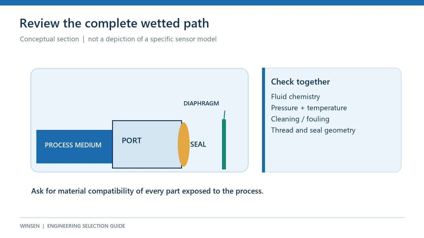
Ask which parts actually contact the medium. Compatibility of a stainless steel housing alone does not establish compatibility of the diaphragm, O-ring, fill fluid, adhesive, or pressure port. Temperature and exposure duration also matter. Request written compatibility confirmation for the exact configuration, especially with aggressive chemicals, oxygen service, refrigerants, or hygiene requirements.
2. Is the required reading gauge, absolute, sealed gauge, or differential pressure?
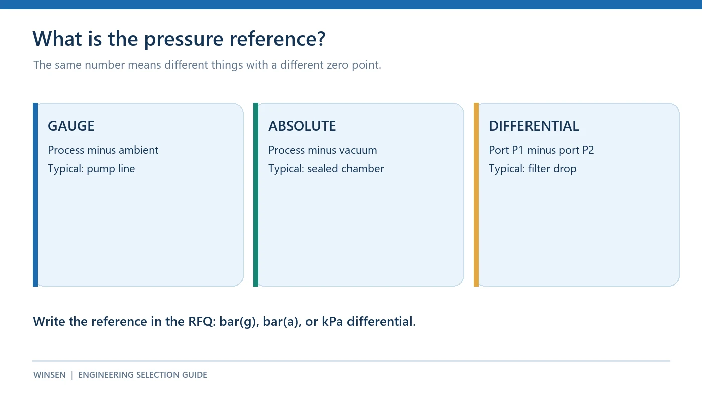
The reference defines zero. Presión de calibre compares the process with ambient atmosphere; presión absoluta compares it with a vacuum reference; presión diferencial compares two process points. A sealed-gauge device uses a fixed sealed reference rather than a live ambient vent. These cannot be exchanged just because the range number is the same.
Write the reference beside the unit: for example, 0–10 bar(g), 0–10 bar(a), or 0–5 kPa differential. A filter pressure-drop measurement needs two pressure points; a single-port gauge transmitter does not directly measure that difference. For more examples, see absolute vs. gauge vs. differential pressure.
3. What are the minimum, normal, and maximum operating pressures?
Write down the lowest and highest values that must be measured accurately, not just the nominal setpoint. Include start-up, shutdown, vacuum conditions, and any reverse pressure. For a pump, a typical running value may be far below the maximum during a blocked discharge or valve transition. The chosen calibrated span must cover the values used by the control system.
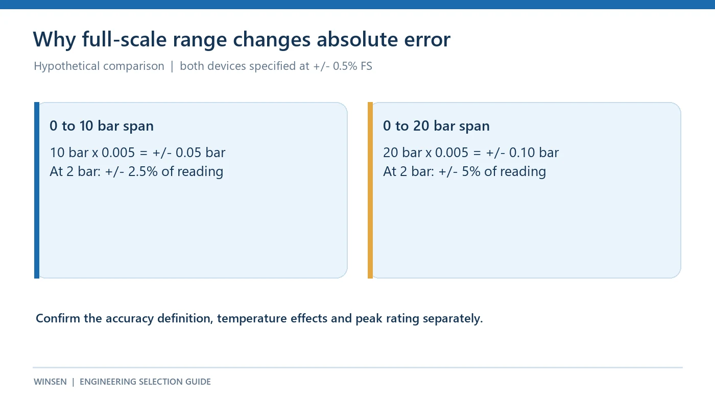
Avoid an unnecessarily wide range. When accuracy is specified as a percentage of full scale (%FS), a larger span gives a larger absolute error at the same percentage. Conversely, a narrow span may leave too little measurement headroom. Use logged pressure traces or a defensible system calculation to establish the actual envelope.
4. What transients, proof pressure, and burst pressure must the device withstand?
Separate measurement range de survival ratings. A transient above the calibrated span may be tolerable for a particular model, but its output may be inaccurate or clipped during that event. Proof pressure describes an exposure the device can survive under a stated test without a permanent shift; burst pressure concerns pressure containment. Their values and definitions must come from the exact model and selected range.
Document the expected peak amplitude, duration, repetition, and direction. Water hammer, pump ripple, hydraulic switching, and pressure testing can create loads absent from steady-state calculations. A snubber or suitable isolation arrangement may help a specific installation, but it can also slow response. Do not apply one universal “two-times range” rule across all devices.

5. What measurement error can the system tolerate?
Begin with the equipment requirement: an alarm threshold, control deadband, process tolerance, or energy calculation. Express the permitted error in pressure units at the important operating points. Then compare it with the sensor’s specification as defined in its data sheet.
“±0.5% FS” is not automatically “±0.5% of reading.” Check whether the stated accuracy includes nonlinearity, hysteresis, repeatability, and temperature effects, and identify the temperature interval over which it applies. Also consider the receiving ADC, excitation or loop supply, installation, and calibration interval. A very small catalog accuracy number does not fix a poorly defined pressure tap or changing process temperature.
6. What temperatures occur at the medium and at the electronics?
Record separate minimum and maximum values for the process medium and the surrounding air. A hot process line can heat a compact transmitter beyond its electronics limit even when the ambient room is cool. Conversely, an enclosure may experience solar heating, cold starts, or condensation beyond the process temperature range.
Distinguish operating temperature de compensated temperature. A device may function over a wider interval than the one where its accuracy has been characterized. If the process is hotter than the sensor’s direct-contact limit, review an appropriate remote seal, stand-off, or other approved mounting arrangement with the manufacturer rather than assuming a standard threaded unit is suitable.
7. How quickly must the installed measurement respond?
Define the required system response: slow trend monitoring, a pump-control loop, or transient capture. A data-sheet response time describes the device under stated conditions. The installed system also contains pressure ports, impulse lines, snubbers, fluid compressibility, filtering, sampling, and controller logic. Any of these can dominate the effective response.
Specify whether you need a step-response time, bandwidth, or sample rate, and at what point in the signal chain it is measured. For rapid hydraulic events, test the complete installation with representative plumbing and electronics. A fast sensor connected through a long, restrictive line may still report a slow event.
8. Which output, supply, and scaling fit the receiving electronics?
List the controller input before selecting an output. Common choices include a bridge-level signal for an OEM analog front end, conditioned voltage for a nearby controller, a 4–20 mA loop for industrial wiring, or a supported digital interface. Each requires the matching supply, wiring, input circuit, and signal scaling. Do not treat “digital output” as enough information: state the protocol, address or baud-rate needs, update rate, and data format.
For a voltage output, specify the voltage at the low and high pressure endpoints and the controller input range. For a current loop, verify the supply and total loop load, including cable and input burden. For I²C, check bus voltage, pull-ups, cable length, and the controller’s interface. The choice is a system-integration decision, not a quality ranking.

9. What process connection and wetted construction fit the equipment?
Write the thread or fitting standard, nominal size, sealing method, installation orientation, allowable torque, and available envelope. “G1/4” and “1/4 NPT” are different connections. Drawings should also identify where the sealing surface sits and whether the pressure port creates a dead volume that can clog or trap air.
For viscous media, particles, or clean-in-place duties, discuss whether a flush diaphragm or a different process interface is needed. Verify every wetted material against the medium and cleaning cycle. A part number should not be approved on the basis of the sensing technology alone; the port and seal may decide whether it works in the process.
10. What will the installation environment do to the sensor?
Record dust, splashing or washdown, immersion, vibration, shock, electrical noise, UV exposure, and cable routing. Then request the enclosure protection and environmental ratings for the complete ordered assembly, including its connector and mating cable. An ingress rating on the body does not automatically cover an unplugged connector or a custom cable exit.
Decide where the electronics and pressure tap can be mounted for service access, drainage, and protection from vibration or water ingress. If a vented gauge reference is used, consider how that reference remains open and dry in the installed design. Include the expected life cycle and maintenance access in the selection review.
11. Which compliance and qualification evidence is required?
The application, not a generic “industrial” label, determines required documentation. Possible needs include material declarations, ingress test information, EMC evidence, calibration records, traceability, and approvals for a hazardous area. Ask for the exact model and configuration documents; family-level marketing statements are not evidence for a specific ordered part.
For a safety-related or regulated system, identify the applicable requirement with your compliance team and request the relevant certificate or test report before release. Do not assume an enclosure rating or an explosion-protection statement on a web page certifies every configuration or installation.
12. What must be fixed before OEM production?
An OEM design needs a repeatable configuration. Freeze the pressure reference and range, output and scaling, supply, port and seal, connector and pinout, accuracy grade, compensation range, labeling, and approved drawing revision. Agree how production tests, calibration, change notices, and replacement parts will be handled.
Validate samples across representative pressure and temperature points and through the real controller. The sample test should include mechanical fit and leak checks, interface behavior at both endpoints, and any relevant environmental exposure. If a requirement changes after testing, treat the replacement as a new configuration to review.
A quick %FS range check
Consider a hypothetical 2 bar operating point and two devices both rated ±0.5% FS under the same stated conditions:
| Calibrated span | Calculation | Maximum absolute error implied by ±0.5% FS | Error relative to a 2 bar reading |
|---|---|---|---|
| 0–10 barras | 10 × 0.005 | ±0.05 bar | ±2.5% |
| 0–20 bar | 20 × 0.005 | ±0.10 bar | ±5% |
The arithmetic shows why “same percent accuracy” can give different useful performance near the bottom of a range. It is no a total installed error budget or a recommendation to choose the smaller span automatically. Compare temperature behavior, proof pressure, transient exposure, calibration terms, and the exact data-sheet definition before deciding.
Copy-ready OEM pressure sensor RFQ
Send a supplier a compact, testable specification. This table can be copied into a request and completed with your project’s values.
| RFQ field | Information to supply |
|---|---|
| Application and medium | Equipment function; fluid/gas composition; cleaning agents |
| Referencia de presión | Gauge, absolute, sealed gauge, or differential; include units |
| Measurement span | Minimum, normal, and maximum readings required |
| Excursions | Peak, reverse, proof, and burst requirements; duration and cycles |
| Required error | Allowable pressure error at critical points; test temperature |
| Temperatura | Process and ambient minimum/maximum; compensation need |
| Dynamic behavior | Response or bandwidth needed at the installed system level |
| Electrical interface | Output, scaling, supply, controller input, wiring length |
| Process interface | Thread/fitting, seal method, wetted materials, drawing envelope |
| Ambiente | IP target, vibration, moisture, EMC and cable/connector needs |
| Documents | Drawings, calibration, traceability and application approvals |
| OEM program | Sample quantity, annual volume, revision and change-control needs |
For example, an RFQ can say: “Please propose a gauge-pressure transmitter for a water-pump controller. We need a defined 0–10 bar(g) measurement span, 24 V DC supply and a 4–20 mA input to our PLC. Please confirm the wetted materials, port and seal drawing, accuracy definition over our temperature range, and proof rating for the specified transient profile.” The values are illustrative requirements, not a claim that a particular model is approved for that installation.
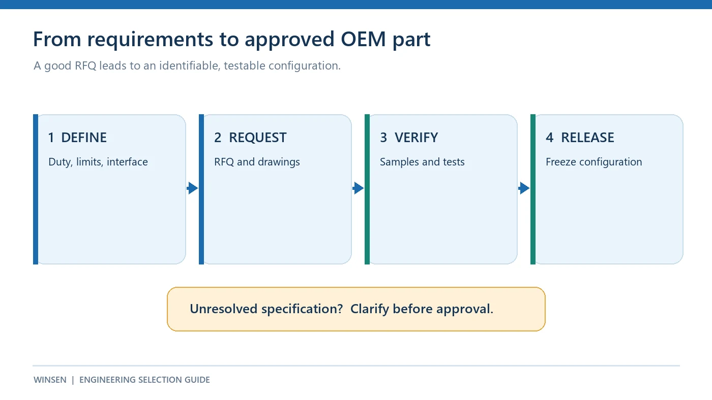
Where three Winsen models may fit
The model comparison is a starting point for a short list. The exact ordered variant still needs confirmation against the official data sheet and application conditions.
| Modelo | Officially described direction | When to evaluate it |
|---|---|---|
| WPCK07 diffused-silicon transmitter | Gauge, absolute and sealed-gauge options; a wide configurable pressure range; current, voltage, I²C and RS485 output options. | Industrial equipment that needs a field transmitter and a confirmed output/port combination. The English site product page provides a local product route. |
| WPCK63 diffused-silicon transmitter | Gauge, absolute and sealed-gauge options from −100 kPa to 6 MPa; 0.2–2.3 V or I²C standard outputs. | Compact OEM systems using the documented voltage or I²C interface. Do not assume a standard 4–20 mA variant. |
| WPCH04 ceramic transmitter | Ceramic piezoresistive construction; listed 0.2–40 MPa range; configurable current and voltage output choices on the official page. | Pump, water, air and similar equipment where the medium, port, pressure reference, output and ordered configuration are confirmed. |
These models address different architectures. A two-port differential measurement, a chemically demanding medium, or a special hygienic interface may require a different product family. Do not infer that all members of one technology family share the same seals, range, or approvals. For a deeper technology discussion, see capacitive vs. piezoresistive pressure sensors.
Review the short list before ordering
Reject any candidate that lacks an answer to a non-negotiable requirement: pressure reference, survival limit, medium compatibility, electrical match, or a required approval. Compare the remaining candidates using the same units and the same error definition. Request the actual ordering code, revisioned data sheet, drawing, and mating connector information.
Finally, test the chosen configuration in the real assembly. The best catalog match is only a candidate until the plumbing, electronics, environment, and production controls have been checked together.
Preguntas frecuentes
How much pressure-range headroom should I allow?
There is no universal percentage. The calibrated range must cover all values you need to measure, while the model-specific proof and burst ratings must address credible excursions. A wider range can increase absolute error when accuracy is stated in %FS, so use your process envelope and the exact data sheet.
Should a pump use a gauge or absolute pressure sensor?
Gauge is common when the control value is pressure above local atmosphere. Absolute is appropriate when the required quantity is referenced to vacuum. State the engineering quantity and unit in the RFQ; do not substitute one reference for another without converting the requirement.
Is 4–20 mA always better than a voltage or digital output?
No. A 4–20 mA loop can be practical for industrial PLC wiring, while conditioned voltage or I²C may suit a nearby embedded controller. Choose the interface that the actual receiver, supply, cable run, and update-rate requirement support.
What is the difference between %FS and % of reading?
For a given span, %FS uses the full-scale span as its base, so its absolute error is approximately fixed under the stated conditions. % of reading scales with the measured value. Read the supplier’s exact accuracy definition; separate temperature and system-level errors may also apply.
How do I confirm media compatibility?
Provide the full process-medium description and temperature, then request the wetted-material list and seal specification for the exact variant. Check compatibility with cleaning chemicals and abnormal exposures as well as normal operation. A housing-material claim alone is insufficient.
Need a pressure sensor for an OEM project? Send Winsen your completed RFQ fields, expected pressure trace, medium, controller input, and mounting drawing. The team can use those facts to evaluate the appropriate pressure sensing options and confirm a configuration for sample testing.

Comment (1)
[…] an overload-survival rating answer different questions. Review both before selecting a span; our industrial pressure sensor buying guide covers the broader range and overload […]