
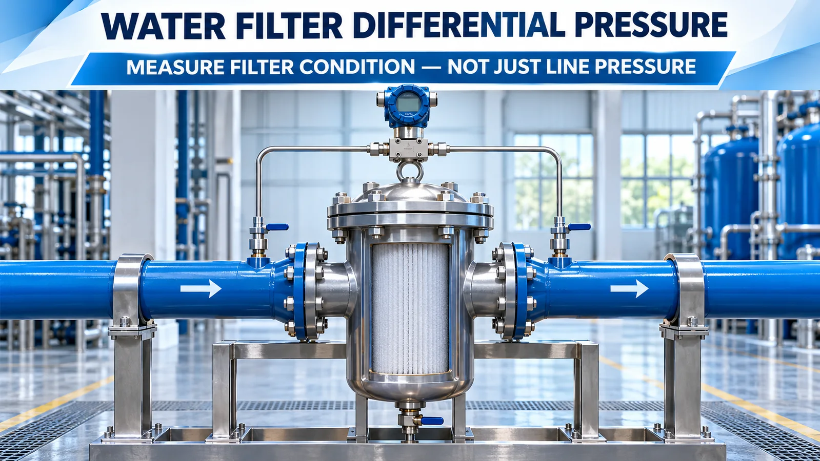
A water filter differential pressure sensor measures the pressure drop from the filter inlet to the outlet. As contaminants accumulate, flow resistance commonly increases and differential pressure rises under comparable operating conditions. That trend can support backwash, cleaning or element-replacement decisions before flow falls too far or a bypass valve opens.
Differential pressure is not a direct dirt meter. It also changes with flow rate, water temperature, viscosity, valve position and blocked pressure taps. A useful monitoring system establishes a clean-filter baseline and records the operating context.
What Does Differential Pressure Across a Filter Mean?
Differential pressure is:
ΔP = P_upstream − P_downstream
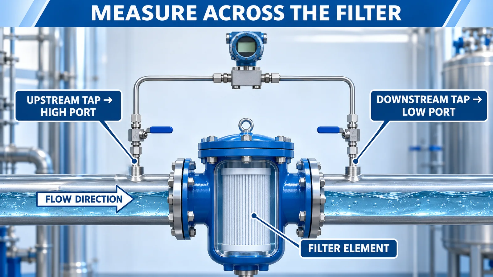
The upstream side normally connects to the high port and the downstream side to the low port. When water is flowing through a clean filter, the element and housing create an initial pressure drop. As trapped material increases restriction, more pressure difference is needed to maintain the same flow.
Các Pall filter-condition guidance explains that differential-pressure indicators compare inlet and outlet pressure and should be read under flow. It also notes that pressure drop increases as contaminants load the filter.
Two separate gauge sensors can be subtracted in software, but a dedicated differential device directly senses the small difference. This is valuable when both sides have high line pressure and the pressure drop is much smaller than either absolute value.
Where Should the High and Low Taps Be Installed?
Install the high-side tap upstream of the filter element and the low-side tap downstream. Both should represent filter inlet and outlet pressure without including unrelated components unless the measurement is intentionally for the entire assembly.
Avoid placing one tap before a control valve and the other after both the valve and filter; the result then combines two pressure losses. Document whether the target is:
- filter element only;
- complete filter housing;
- strainer and valve assembly;
- membrane stage;
- multimedia vessel;
- an entire treatment train.
Use approved isolation and equalizing valves where the design requires them. Route both impulse paths to avoid gas pockets in liquid measurement. Flush debris before connecting the sensor, and protect the pressure ports from maintenance damage.
Các pressure types guide explains why differential pressure compares two process points rather than a single point with atmosphere.
Establish a Clean-Filter Baseline
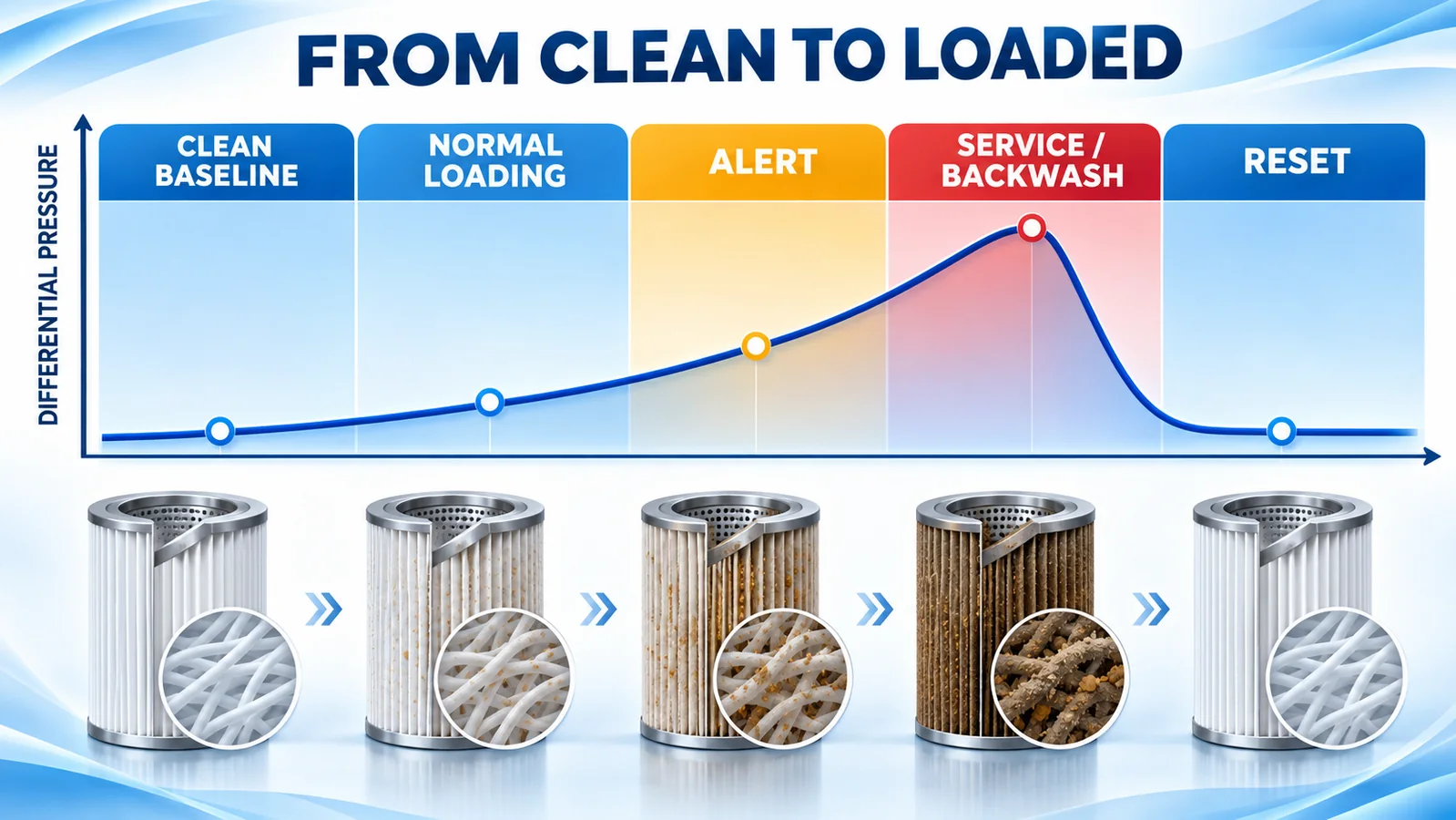
After installing a new or cleaned element, stabilize the system at a defined condition and record:
- flow rate;
- inlet and outlet pressure;
- differential pressure;
- water temperature;
- valve positions;
- pump speed or operating mode;
- filter model and element lot;
- sensor zero and calibration status.
This clean baseline is more useful than assuming zero differential pressure. A real clean element has pressure loss. The baseline should be repeated at the same design flow after maintenance so the reset can be compared.
Track both the value and the rate of change. A slow rise over weeks may represent normal loading. A rapid rise over minutes may indicate a process upset, collapsed media, valve movement or blockage.
Why Must Flow Be Recorded?
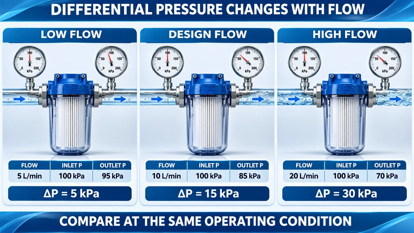
Pressure drop increases with flow, even when the filter condition does not change. The relationship may not be linear and depends on element geometry and flow regime. If pump speed doubles or a downstream valve opens, differential pressure can rise without additional dirt.
Compare filter condition at the same or normalized flow. Useful strategies include:
- record differential pressure only within a defined flow band;
- trend both flow and differential pressure;
- use the filter manufacturer’s flow-versus-pressure-drop curve;
- create a validated normalized indicator for variable-flow systems;
- pause maintenance alarms during no-flow states while retaining diagnostic events.
Water temperature changes viscosity and therefore pressure loss. This is especially important for seasonal water, hot cleaning cycles and liquids more viscous than water.
Set Alert, Backwash and Replacement Logic
Thresholds should come from the filter, membrane or system manufacturer and from validated operation. Do not copy one differential-pressure value across cartridge, bag, sand, membrane and self-cleaning filters.
A practical control structure separates:
- normal operating band;
- early alert;
- backwash or cleaning trigger;
- element-replacement limit;
- high-high protective action;
- bypass-valve opening point;
- sensor or tubing fault states.
Use time delay or persistence to reject very short pump and valve transients, but do not delay a condition that can damage the element or force bypass. Alarm logic should consider flow: high differential pressure at zero flow may indicate trapped pressure, valve arrangement or measurement fault.
For automated backwash, verify that differential pressure falls toward the established clean value afterward. A completed command without a pressure reset may mean the backwash was ineffective.
What Can the Trend Shape Diagnose?
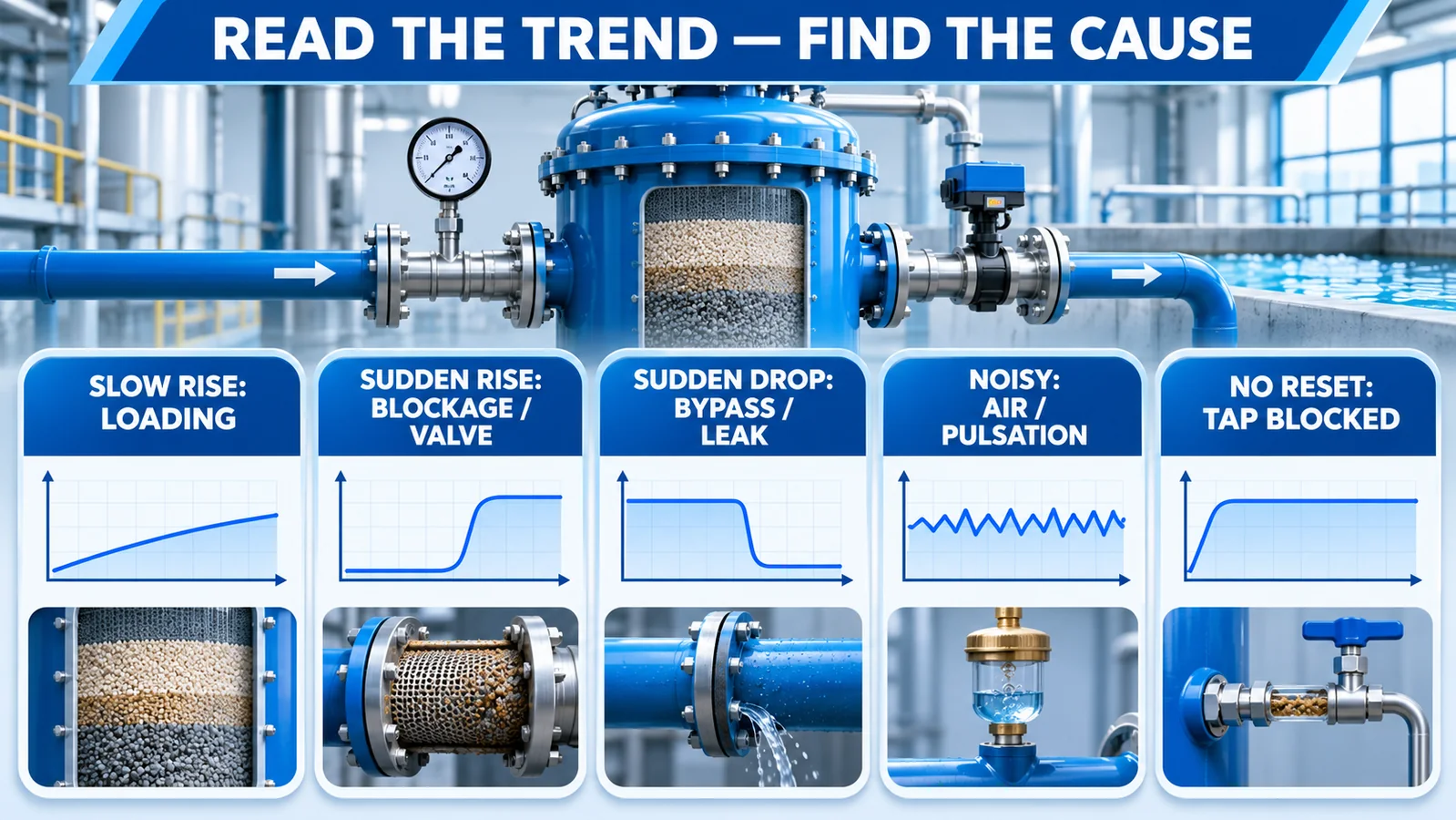
Slow, steady rise
Often consistent with normal contaminant loading when flow and temperature are stable.
Sudden rise
Check for a flow increase, downstream valve movement, blocked outlet, media collapse, rapid solids event or blocked low-side line.
Sudden drop
Check for reduced flow, bypass opening, torn element, housing leakage, high-side tap blockage or a sensor fault. A low reading is not automatically good filter condition.
Noisy differential pressure
Look for pump pulsation, air in impulse lines, cavitation, loose tubing, electrical noise or a sensor range too narrow for the transient environment.
Differential pressure does not reset after service
Check that the correct element was changed, valves returned to position, taps were flushed, both lines are open and the sensor was properly zeroed.
Select Differential Range and Static Pressure Rating
A differential sensor must satisfy two different pressure requirements:
- the differential range across the filter;
- the line or common-mode pressure applied to both ports.
A 0–100 kPa differential range does not imply both ports can safely accept any line pressure. Review maximum static pressure, one-sided overpressure, reverse differential and burst/containment limits from the exact data sheet.
Choose a range that covers the clean-to-service differential plus credible transients without making normal changes too small to resolve. Review accuracy, hysteresis, repeatability, temperature effects and long-term stability separately.
The article on pressure sensor repeatability, hysteresis and resolution explains how to verify small changes in the complete signal chain.
Dedicated DP Sensor vs Two Gauge Transmitters
Two gauge transmitters can be useful when operators also need the individual inlet and outlet pressures. The control system subtracts synchronized values to obtain differential pressure. However, each transmitter contributes zero error, span error, temperature drift and timing uncertainty.
For example, detecting a 20 kPa drop by subtracting two 1 MPa-range transmitters can be difficult if each channel’s pressure-unit uncertainty is a significant fraction of 20 kPa. A dedicated DP sensor directly measures the smaller difference and can provide better sensitivity, but it must withstand the common line pressure on both ports and any one-sided event during valve operation.
Some systems use both: gauge transmitters for line protection and a dedicated DP channel for filter condition. Choose based on the required diagnostics, uncertainty budget, static pressure and maintenance strategy.
Media, Seals and Impulse Lines
Both sides of a water-filter sensor may contact feed water, chemicals, disinfectants, cleaning fluids or concentrated contaminants. Review diaphragm, housing, seals, tubing and process fittings.
Các danh sách kiểm tra vật liệu ướt cảm biến áp suất helps identify every exposed component. Potable water, seawater, wastewater and chemical-cleaning service are different compatibility cases.
Impulse lines can freeze, grow biofilm, trap gas, collect sediment or leak. A maintenance plan should include isolation, flushing, inspection and leak testing without contaminating the water system.
How Does WPAK67 Fit?
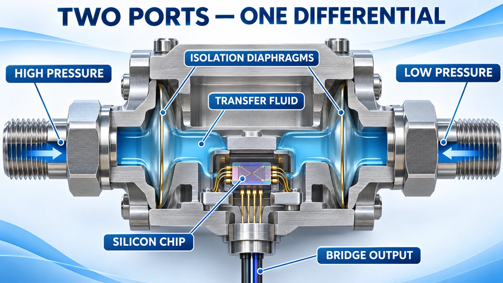
hiện tại Winsen WPAK67 page describes an isolated differential-pressure core using stainless-steel double-corrugated diaphragms, silicone-oil pressure transfer and a silicon sensing chip. The page lists a millivolt differential bridge output, a range family from 0–10 kPa to 3.5 MPa and 316L stainless-steel diaphragms.
WPAK67 is a raw sensor core, not a finished 4–20 mA water-filter transmitter. An OEM must design excitation, amplification, compensation, calibration, housing, connectors and process interfaces. The official page also lists seal options, so compatibility must be checked for the ordered construction and actual water chemistry.
The final assembly must be qualified for maximum static pressure on both ports, one-sided overload, temperature, vibration, moisture ingress and long-term zero stability. Request the current manual and range-specific data.
quan chức WPAK67 manual is the starting point for electrical excitation, bridge output and range-specific characteristics. Confirm that the supplied revision and ordered seals match the final design.
For a broader overview of water pressure applications, see the Winsen water pressure sensor guide.
Commissioning and Maintenance Checklist
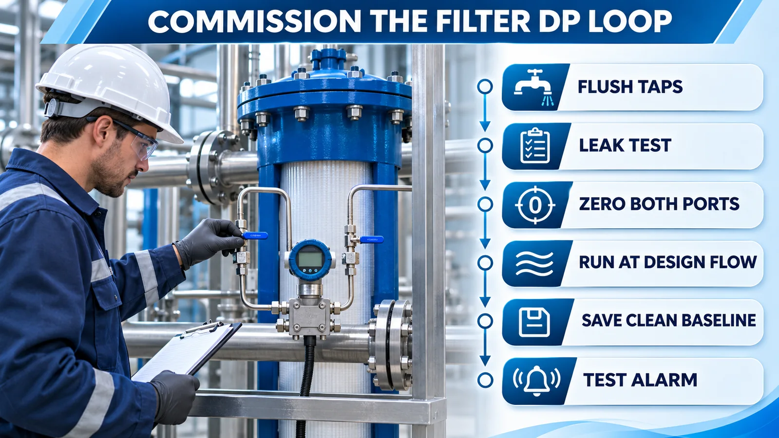
- Confirm flow direction and filter boundary.
- Verify upstream-to-high and downstream-to-low connections.
- Flush taps and impulse lines before sensor connection.
- Leak-test both paths.
- Equalize both ports and verify zero according to the procedure.
- Start at low flow and check for trapped gas or shock.
- Run at design flow and save the clean baseline.
- Test alert, service and fault logic.
- Record flow, temperature and valve state with the trend.
- After cleaning or replacement, confirm the expected differential reset.
Common Commissioning Traps
Do not save the “clean baseline” while the system is still venting air, running below design flow or using temporary startup valves. Confirm the element is seated correctly and the housing is fully flooded where required. Equalizing the ports proves sensor zero but does not prove that both process taps are open and representative.
When testing alarms, simulate a pressure difference through an approved calibrator or controlled process condition rather than closing arbitrary valves that could overpressure one side. Verify the complete path from sensor output to PLC scaling, alarm message, maintenance notification and event history. Finally, return every isolation and equalizing valve to its documented operating position and independently check it.
Câu hỏi thường gặp
Does higher differential pressure always mean a dirty filter?
No. Higher flow, colder or more viscous liquid, valve changes and blocked impulse lines can also increase the reading.
Can I subtract two gauge transmitters?
Yes, but uncertainty from both devices can be large compared with a small pressure drop. Synchronization and range also matter. A dedicated DP sensor may be more suitable.
Should differential pressure be zero when the filter is clean?
Usually not under flow. A clean element and housing create an initial pressure drop.
Can the sensor trigger automatic backwash?
Yes, as part of validated logic that also considers flow, time, valve state and post-backwash pressure recovery.
Phần kết luận
A water filter differential pressure sensor is most useful when its high and low taps define the filter boundary, a clean baseline is recorded at known flow, and trends are interpreted with temperature and operating state. Select both the differential range and static pressure capability, then verify the complete tubing and alarm loop. For OEM integration, liên hệ Winsen with filter type, flow, line pressure, expected differential range, water chemistry and output requirement.
