
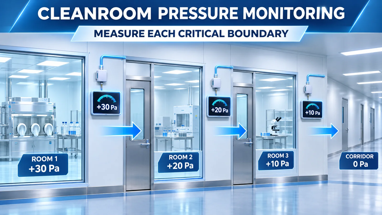
Cleanroom pressure monitoring measures the differential pressure between a controlled room and a defined adjacent space. Positive pressure helps drive air from a cleaner area toward a less clean area when that direction supports the contamination-control strategy. A number without the two compared locations is incomplete.
Reliable monitoring begins with a pressure-cascade map, then places representative static-pressure taps on each critical boundary. The sensor, tubing, alarm logic, door behavior, HVAC response and data record must be qualified as one system.
What Does Cleanroom Differential Pressure Protect?
Room pressure is one part of controlling airflow and contamination movement. In a positive-pressure arrangement, the higher-classified or more protected space is maintained above an adjacent lower-pressure space so leakage airflow tends to move outward.
Some processes need negative pressure for containment instead. The correct direction follows the process hazard and contamination-control strategy, not a universal assumption that every cleanroom must be positive.
. WHO sterile-products GMP guidance calls for differential-pressure indicators between relevant cleanrooms and identifies continuous monitoring, recording and warnings for critical differentials. Exact requirements depend on facility scope and governing regulation.
Map the Pressure Cascade Before Selecting Sensors
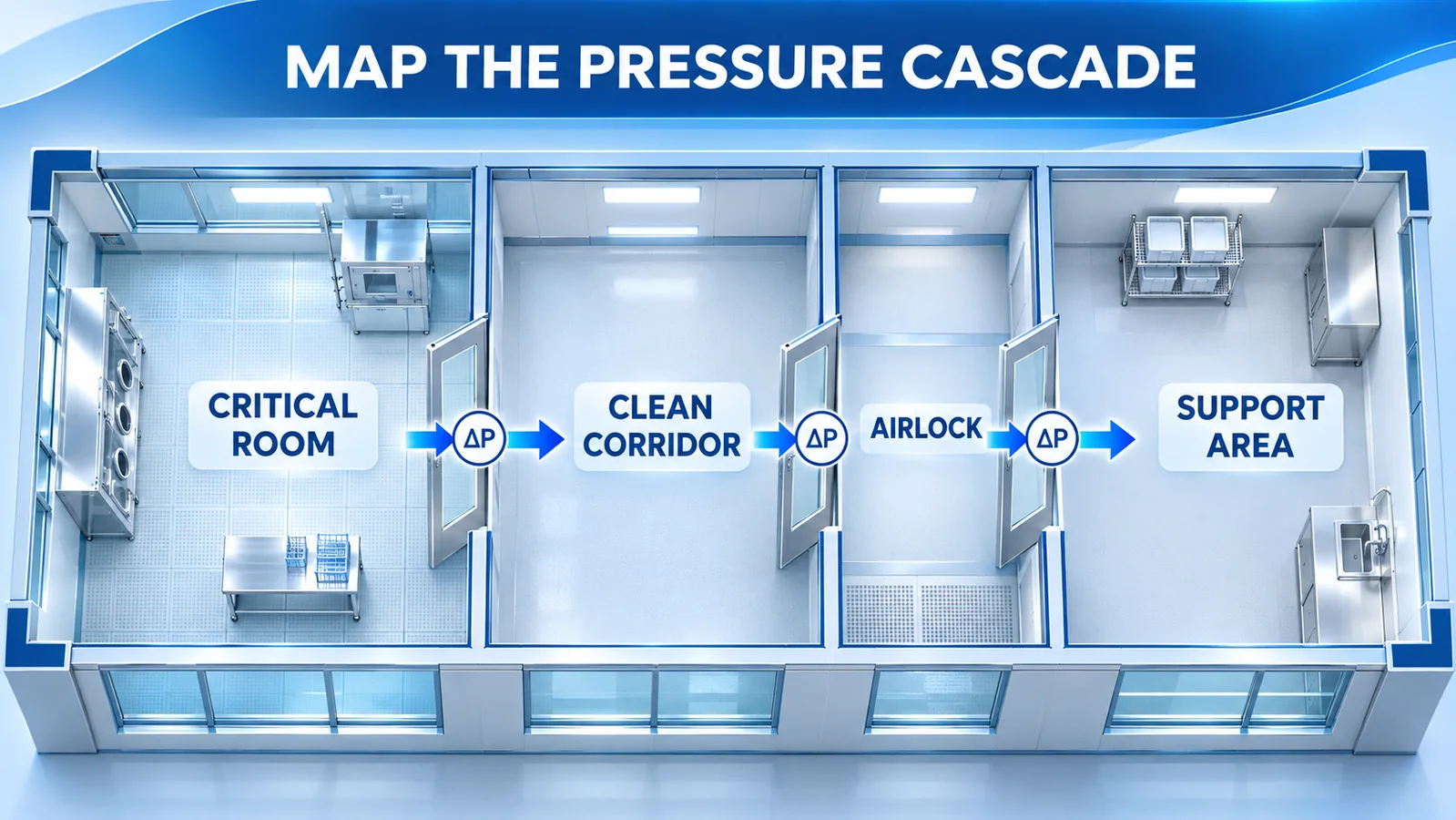
List each room, classification or cleanliness role, process risk and intended airflow direction. Then identify the physical boundary that must be measured:
- critical room to clean corridor;
- clean corridor to support area;
- airlock to each connected room;
- isolator or enclosure to its background;
- containment room to adjacent space;
- room to outdoor or building reference where applicable.
Draw an arrow for intended airflow across every door, pass-through and leakage path. Assign a differential-pressure measurement only after both sides are defined. One sensor from a central reference may be convenient, but it may not prove every local boundary.
The general differential pressure guide explains the P_high − P_low relationship. Cleanroom design adds the practical question: which two spaces must remain ordered during real operation?
Where Should Pressure Taps Be Placed?
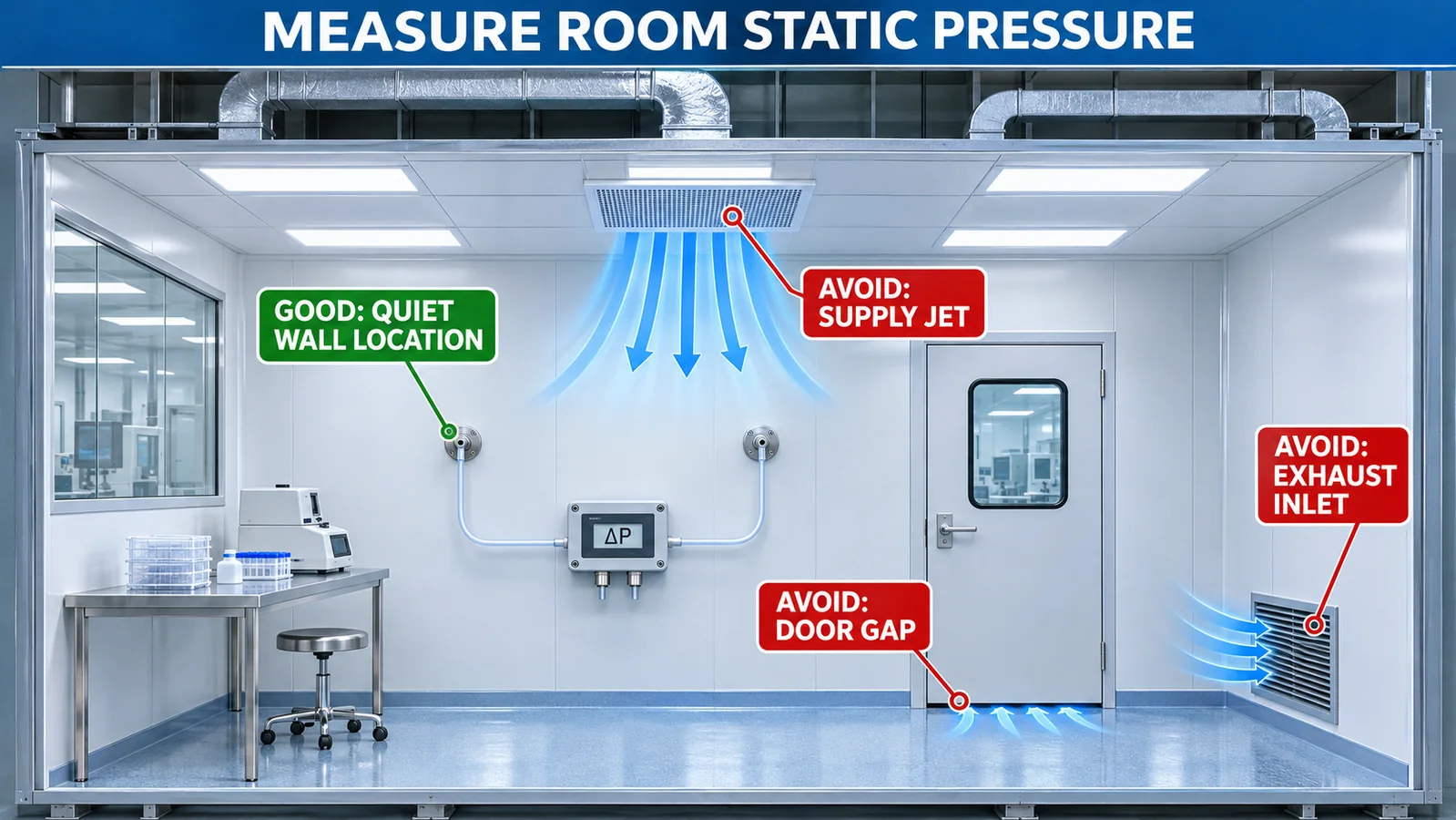
A tap should sense room static pressure, not velocity pressure from a nearby air jet. Avoid locations directly in:
- supply diffuser discharge;
- return or exhaust inlet flow;
- door-gap leakage jet;
- fan or process exhaust plume;
- a frequently bumped work zone;
- direct cleaning spray or condensation.
Place paired taps so each represents its room side of the same boundary. A wall-mounted room tap with a smooth, cleanable face is often preferable to an open tube projecting into the space. Location should remain accessible for inspection without disrupting critical operations.
Do not place both taps on the same side of a door or assume a ceiling plenum is the room reference. Document wall, height, room served and high/low assignment on drawings and labels.
Connect High and Low Ports Correctly
For a positive room relative to a corridor, connect the room tap to the high port and the corridor tap to the low port when the desired display is a positive number. Reversed tubes produce negative readings or inverted trends.
The sign convention should be stated in the functional specification. Operators need to know whether +15 Pa means Room A is above Corridor B or the reverse. Use labels that name the spaces, not only “H” and “L.”
A bidirectional sensor is useful where pressure can reverse and the direction matters. A unidirectional range may provide more usable span when reversal is impossible or treated as a fault, but verify overload on both ports.
How Should Differential Tubing Be Installed?
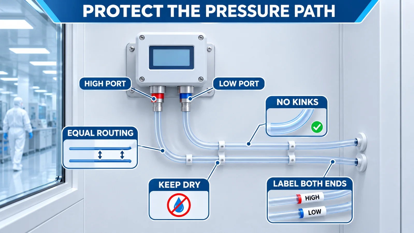
Tubing is part of the measurement. Leaks, kinks, loose fittings, moisture and blocked taps can create a false reading. Use material compatible with cleaning agents and the environmental requirements of the space.
Good practice includes:
- keep routes as short and simple as practical;
- avoid sharp bends and compression damage;
- secure tubing without pinching it;
- label both ends with the room name and port;
- prevent condensation pockets;
- protect the sensor from cleaning liquid;
- leak-test the complete path;
- record tubing length and internal diameter when response time matters.
Long unequal tubing can create different response delays. For low differential pressure, small leaks or trapped moisture can be as important as the sensor’s catalog accuracy.
One Sensor per Boundary or a Shared Reference?
A dedicated sensor across each critical boundary gives a direct, easy-to-explain measurement and limits the effect of one tubing fault. A shared reference manifold can reduce sensor count, but changes in the reference space or manifold leakage can affect several channels at once. Long remote lines also increase response time and maintenance effort.
Choose the architecture through risk assessment. Draw every pneumatic connection, identify common-cause failures and define how a failed reference is detected. If software subtracts two separate room-pressure transmitters, include the uncertainty, synchronization and drift of both channels; a small differential can be hidden inside two larger independent errors.
Airlocks and Door-Opening Events
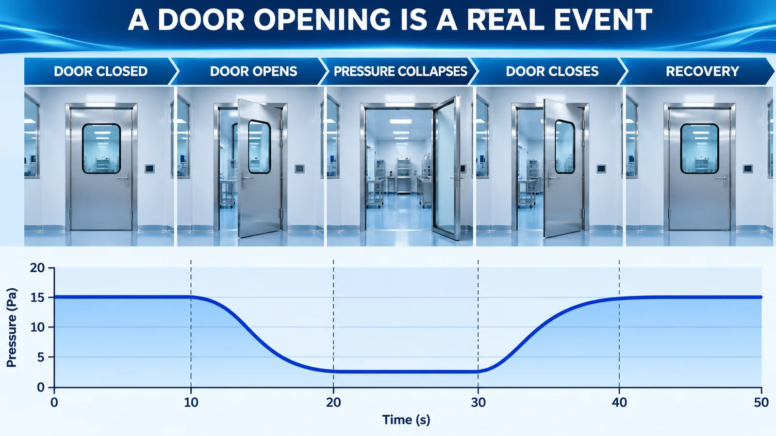
Opening a door temporarily connects two spaces with a large flow area, so differential pressure commonly collapses or reverses. The control system then recovers after the door closes. This is a real physical event, not automatically a sensor fault.
Characterize:
- pressure before opening;
- minimum and reversal during opening;
- door-open duration;
- recovery time after closure;
- interaction with the second airlock door;
- effect of people, carts and process exhaust.
Interlocks, door discipline and HVAC control should support the pressure strategy. Alarm delays may prevent nuisance alarms from an approved short door cycle, but the delay must be justified. It should not conceal a door left open, simultaneous airlock opening or slow HVAC recovery.
Do Not Copy One Pressure Setpoint Everywhere
Some guidance provides example pressure differentials within a defined regulatory scope. For example, FDA aseptic-processing guidance discusses 10–15 Pa between certain adjacent rooms of differing classification. That is not a universal target for every cleanroom, industry or boundary.
Setpoints and alarm bands should follow:
- governing regulation and product requirements;
- contamination-control or containment risk;
- room classification and airflow studies;
- door and exhaust transients;
- HVAC control capability;
- sensor uncertainty and drift;
- qualified normal operating data.
The difference between setpoint, alert level and action level should be explicit. Leave enough operating margin that measurement uncertainty and normal control variation do not consume the alarm band.
Select Range, Resolution and Static-Pressure Capability
Choose a differential range close enough to the qualified operating band to provide useful resolution, with credible bidirectional and overload margin. A sensor with a very broad kilopascal range may technically survive but provide poor usable resolution for a low-Pascal room differential.
Also check maximum static or common-mode pressure: both ports may sit near atmospheric or another common pressure while their difference is small. For board-level sensors, pressure-port orientation, tubing load, PCB stress and enclosure airflow can influence performance.
Review accuracy, zero drift, temperature compensation, resolution, response time and long-term stability as separate specifications. The repeatability, hysteresis and resolution guide explains why a high ADC bit count alone does not guarantee usable room-pressure resolution.
Alarm, Delay and Trend Design
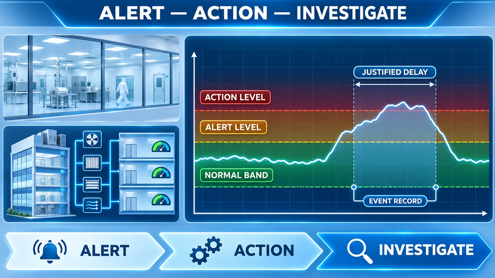
. ISO 14644-2 monitoring framework emphasizes a monitoring plan, trend information and user-defined alert and action levels. Apply that risk-based thinking to pressure even when another standard or procedure controls the exact requirements.
Record at least:
- value, unit and sign convention;
- compared room names;
- timestamp and sensor identity;
- door and HVAC operating state when available;
- alert/action event and acknowledgement;
- calibration and maintenance status;
- change-control revision.
Trend recovery time, frequency of pressure reversals and time near alert levels—not only daily minimum and maximum. Repeated short disturbances can reveal door, balance or control problems before a sustained failure occurs.
How Does WPAS13 Fit?
Mevcut Winsen WPAS13 page describes a MEMS digital micro differential-pressure gas sensor with an I²C interface, digital compensation and 24-bit ADC. The page lists a -100 to 100 kPa family, ±1% FS accuracy, -5 to 65 °C working temperature and customizable ranges.
WPAS13 is a board-level component, not a finished validated cleanroom monitor. An OEM must select the exact range, design pressure connections and enclosure, provide power and digital integration, qualify usable low-pressure resolution, manage zero and drift, and meet facility requirements for display, alarms, recording, calibration access and cleaning.
Do not infer that the broad family range is appropriate for a specific low-Pascal boundary. Request the exact-range data and evaluate the complete monitoring assembly.
Resmi Winsen pressure-sensor catalog provides the wider family context, but the final selection still needs exact-range performance and application approval. A catalog listing cannot establish cleanroom compliance or a qualified alarm function.
Plan a field zero check that does not confuse equalized pressure with a normal operating room condition. An approved valve or temporary equalization arrangement can place both ports at the same pressure, but it must not create an uncontrolled opening between classified spaces. Record the zero result before adjustment, restrict adjustment authority and investigate repeated zero movement instead of continually trimming it away.
Commissioning and Periodic Verification
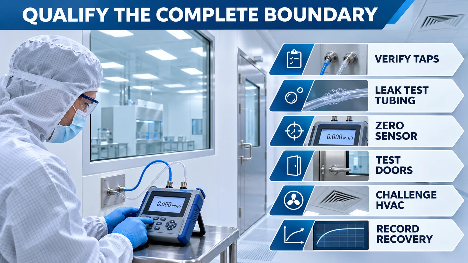
- Verify every tap against the pressure-cascade drawing.
- Confirm high/low port assignment and sign.
- Leak-test and inspect tubing.
- Zero and calibrate with a suitable low-pressure reference.
- Compare local indication, BMS value and recorded data.
- Open doors and challenge expected operating states.
- Test HVAC loss, exhaust changes and recovery where approved.
- Verify alert/action limits, delay, notification and event retention.
- Document normal bands and recovery times.
- Establish calibration, zero-check and tubing-inspection intervals.
WHO HVAC guidance states that pressure control and monitoring devices should be calibrated and that transient effects such as extract systems should be considered. Calibration of the sensor alone is not enough if tubing leaks or the tap is unrepresentative.
SSS
Should the cleanroom tap always connect to the high port?
Only when the room is intended to be positive relative to the compared space and a positive display is desired. Define the sign convention explicitly.
Can one corridor reference serve many rooms?
It can be part of a designed system, but verify tubing response, manifold effects and whether the corridor pressure is representative at every boundary.
Should door openings always trigger an alarm?
The alarm behavior should follow qualified door cycles, risk assessment and governing requirements. Any delay must be justified and tested.
Is a digital differential-pressure sensor automatically a monitoring system?
No. A complete system also needs taps, tubing, enclosure, display or interface, alarms, records, calibration and qualification.
Çözüm
Cleanroom pressure monitoring is boundary monitoring. Map the intended pressure cascade, place static-pressure taps away from local jets, protect and label the tubing, qualify door transients and set alarms from risk and operating evidence. For OEM sensor integration, Winsen'la iletişime geçin with the required differential range, gas, temperature, interface and system architecture.
