
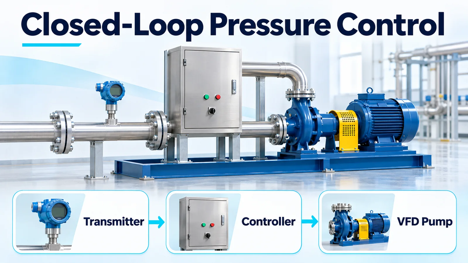
A closed-loop pressure control system uses a transmitter to measure pressure, a controller to compare that measurement with the setpoint, and a variable frequency drive to change pump speed. For a typical discharge pressure loop, the controller requests more speed when measured pressure is below target and less speed when it is above target. Reliable control starts with a meaningful feedback point and correct pressure scaling. Tuning comes after those checks.
The controller can reside in the drive, a PLC or a packaged pump controller. Assign one device ownership of the loop. If a supervisory system changes the target, define how it does so, how often it updates the value and what happens on loss of communication. Save the active target, measured pressure and controller output together so a trend reveals whether the pump responded to demand or to a new setpoint.
Which Pressure Should the Controller Hold?
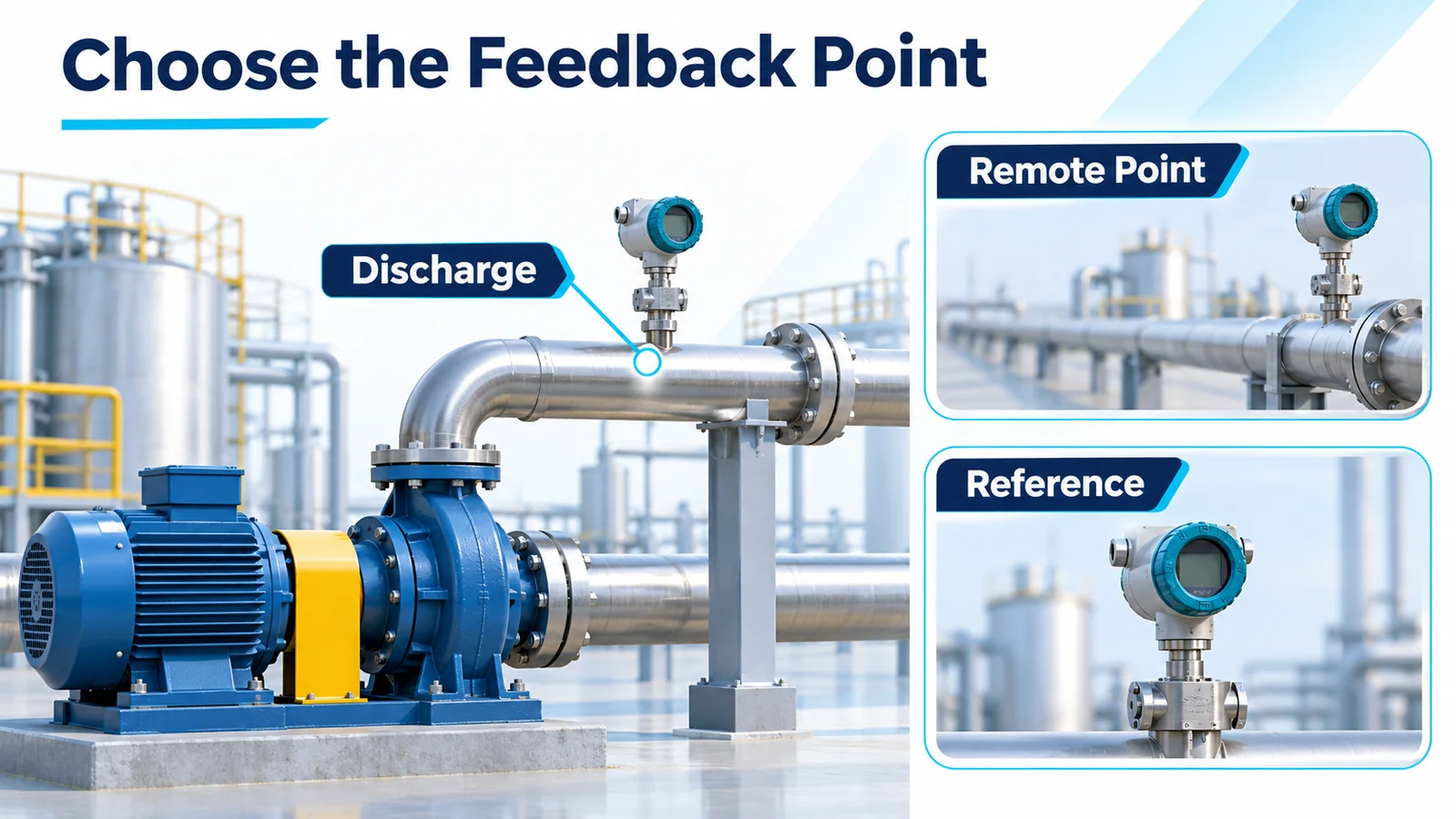
A discharge manifold transmitter is practical when the intended controlled variable is skid outlet pressure. The Grundfos Hydro Multi-B instructions describe a packaged system that uses manifold pressure feedback and adjusts running speeds or stages more pumps. A discharge reading responds quickly to pump changes, is generally accessible and is easier to validate during skid testing.
If the service objective is minimum pressure at a remote consumer, pipe losses can make a constant skid outlet pressure an imperfect proxy. For example, at 400 kPa at the skid, a path with a net pressure decrease of 80 kPa leaves 320 kPa downstream. At lower flow, a decrease of 20 kPa leaves 380 kPa. Specify the allowable controlled pressure at both points before choosing remote sensing or a monitored local setpoint strategy. Elevation head and pressure losses should be considered separately during design.
A remote sensor adds dependence on signal transport and can be influenced by branch demand. The local transmitter may still serve as a monitor or operating limit. Use controlled transfer if a system can switch feedback sources and define the permitted operating envelope for fallback. See the booster pump sensor selection guide for position and range selection.
How Do You Scale the Input Before Tuning?
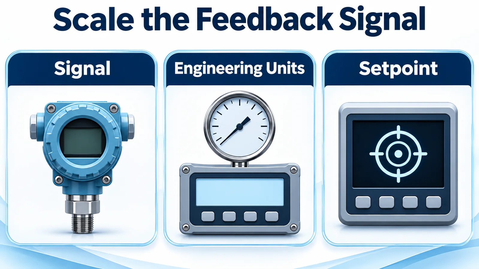
Record the pressure reference, lower range value, upper range value, signal type and engineering units. Configure the receiving channel for the exact ordered output and check pressure conversion at more than one known point. On a linear 0–1 MPa gauge transmitter with a 4–20 mA output, 4 mA represents 0 kPa, 12 mA represents 500 kPa and 20 mA represents 1,000 kPa. For a 400 kPa target the expected signal is 10.4 mA. A drive that interprets the input using a different range can reach a steady reading at the wrong physical pressure.
The controller may use percent internally. Confirm what is displayed and what the supervisory system writes. A target of 40% on a 0–1 MPa input is 400 kPa. The same number could mean something different on another controller or after replacing the transmitter. Label units in the HMI, alarm list and history.
Compare the raw input and drive calculation against an independent pressure reference at the approved test point. Check plausibility and signal quality before allowing automatic operation. For active and passive inputs and loop voltage checks, see the two-wire 4–20 mA guideПолем
How Do You Tune a Pressure Loop With a VFD?
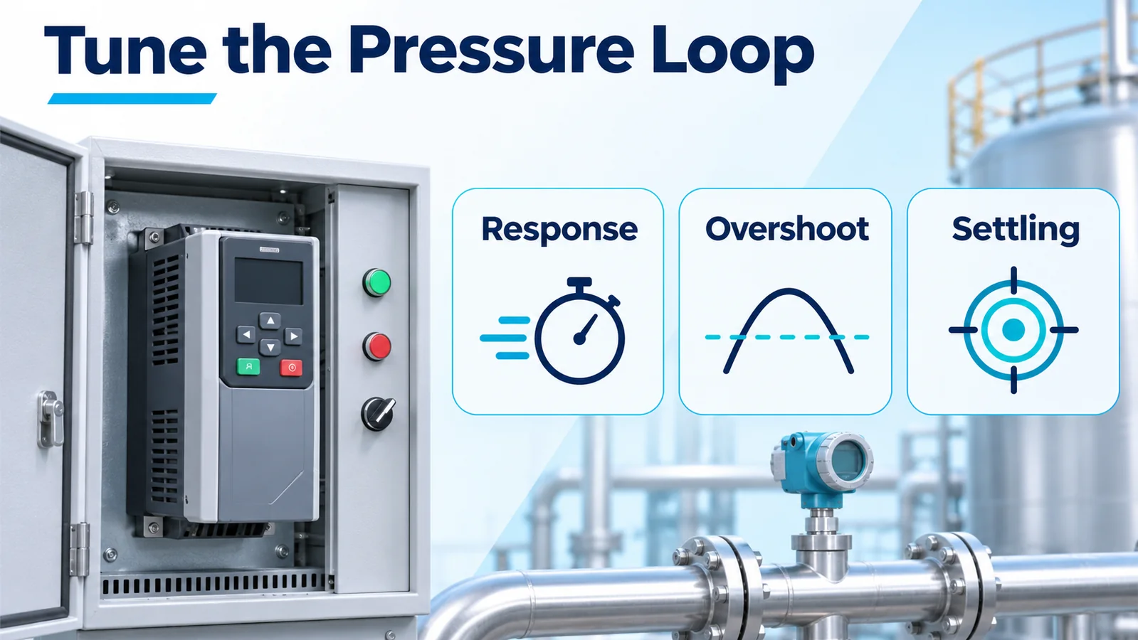
Begin with the equipment manufacturer’s commissioning instructions. Record the controller convention, because names such as direct and reverse action vary by implementation. Make a controlled verification that a drop below setpoint requests the intended increase in pump output when the process and permissives allow it. Confirm the observed process response as well as the displayed command. An incorrectly signed loop can drive the pump to a limit quickly.
Many pressure loops can be commissioned using proportional and integral action. Proportional action responds to current error. Integral action accumulates error and can remove a sustained difference within the controllable operating range. Excessive response can create overshoot or repeated oscillation, especially where a tank, long pipe, restrictive sensing port, slow signal path or drive ramp adds delay. There is no general gain setting that transfers safely between skids.
Log pressure feedback, setpoint, commanded and actual speed, drive limits, pump status and available flow. Observe a repeatable, approved demand change. Use the timing between each trend to find where delay begins. A speed change followed by late pressure response points to the process or sensing path. A slow change in actual speed despite a quick command points to ramp or drive limits. Oscillation with every analog input update suggests a measurement or filtering issue worth resolving before changing gains.
Check behavior when speed reaches the minimum or maximum. Integral windup can leave pressure slow to recover after the constraint clears. Use the controller’s supported integral limiting or tracking features where available. Review how manual to automatic transfer initializes the output and how feedback filters affect settling time. Preserve a trend with the original parameters before making a documented change.
What Happens During Pump Staging and Low Demand?
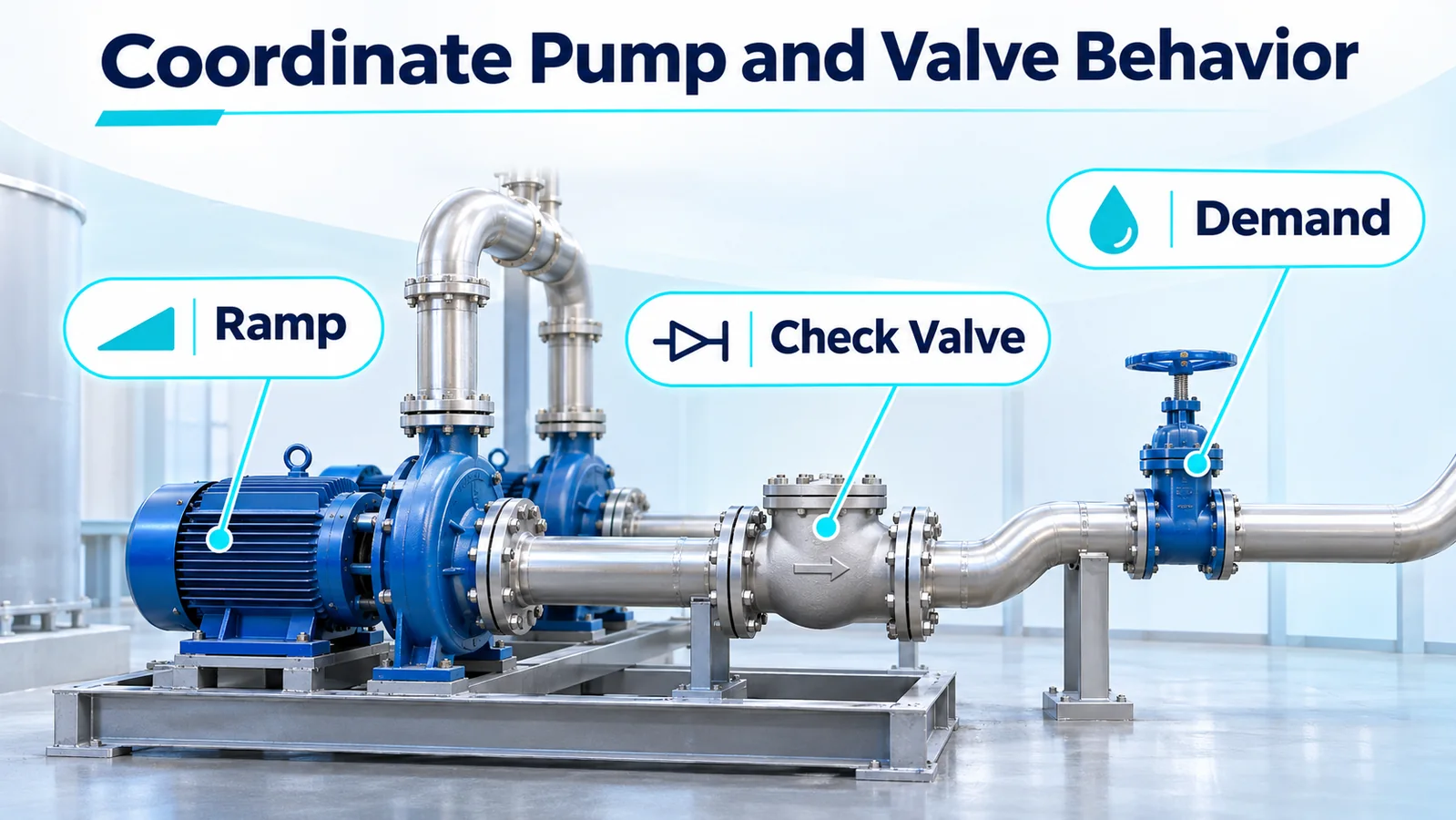
Minimum speed protects the operating envelope but may still deliver more flow than the system needs. In a supported sleep mode, the system can stop the pump after verified low demand, then restart according to the configured condition and delay. A pressure vessel may buffer demand while the pump is stopped. A leaking check valve or an incorrect vessel precharge can shorten that interval and create repeated starts. Trend pressure decay, pump state and downstream demand together before changing sleep parameters.
On a multi-pump skid, the controller may stage another pump when feedback stays below target and the running pump approaches its usable capacity. Stage transitions can expose slow check valves, mismatched speed commands or poorly coordinated control. Record when each pump actually starts or stops. Test both staging and destaging with the allowed demand scenarios, since the hydraulic transient and recovery can differ in each direction.
Drive ramps influence flow transitions. Faster speed changes may improve a measured settling time while creating pressure transients elsewhere in the piping. Review allowable ramp and surge behavior with the skid and piping design. The water hammer protection guide explains why a slow control trend can miss a short peak at the sensor port.
Which Faults Need Separate Responses?
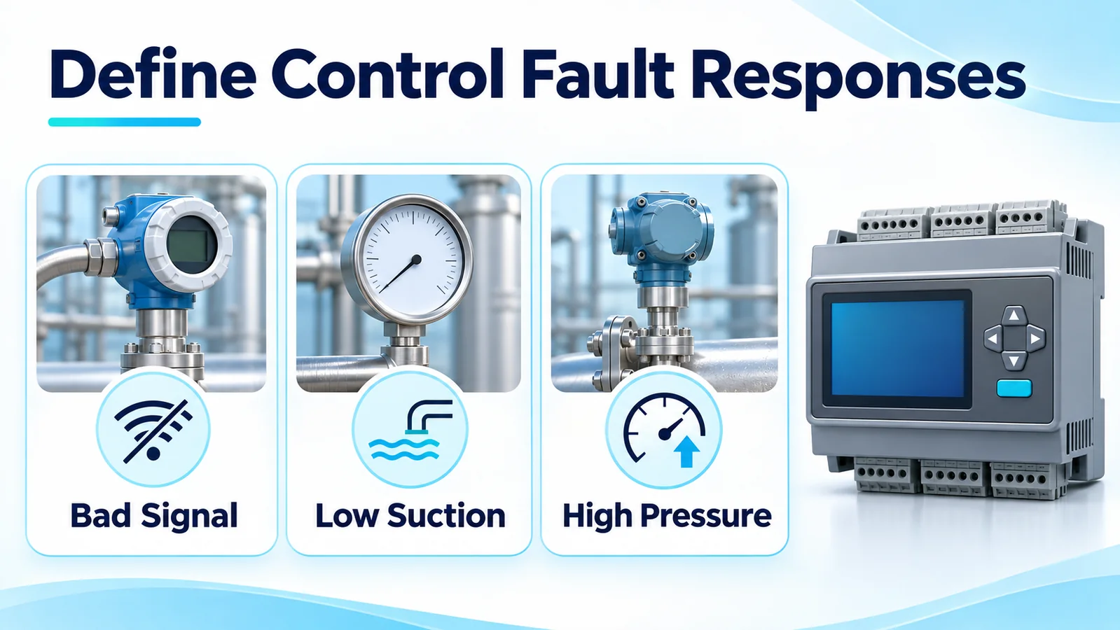
| Состояние | Check first | Design decision |
|---|---|---|
| Missing, stale or invalid feedback | Raw input, loop current, fieldbus age and quality | Define an approved stop, hold or limited fallback and its duration |
| Pressure low with speed at maximum | Suction condition, actual speed, pump capacity and demand | Alarm on persistent inability to meet target and inhibit further escalation when limits apply |
| Pressure high at minimum speed | Pressure validity, controller ownership, valve state and sleep logic | Define the allowed stop and restart behavior |
| Low suction or dry-run risk | Inlet reference and process permissives | Implement the protection required by the equipment design |
| Overpressure or rapid transient | Independent reference and protection devices | Review protective limits and the appropriate separation from the regulating loop |
A control feedback transmitter can inform a fault response, but the level of independence and protection depends on the equipment and risk assessment. Confirm what happens if the signal remains plausible while frozen. For a digital interface, use update age or quality when available and test the defined communications loss response. For an analog loop, distinguish configured under-range and over-range diagnostics from a valid low-pressure value, using the transmitter and input documentation.
An indicated pressure that is flat can be valid at stable demand. It can also result from a blocked tap, stale registers or a controller displaying a substituted value. Compare the raw value, quality and local reference during a known permitted change. Document substitutions on the operator screen so a fallback value cannot be mistaken for current measured pressure.
How Do You Commission Under Representative Demand?
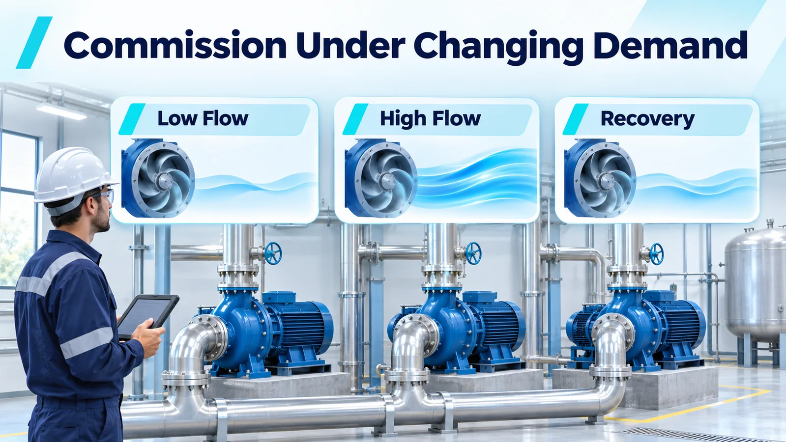
Write the acceptance criteria before testing. Include allowable steady pressure error, overshoot, recovery time, start frequency, valid speed range and the intended fault response. Specify where each criterion is measured. A remote service boundary and a skid pressure limit can have different values and both deserve recorded trends.
- Verify tag identifiers, transmitter range, pressure reference and input scaling against the approved design.
- Verify actual pressure independently at the appropriate point, including a second check near the working setpoint.
- Confirm command direction, feedback update and drive limits in the intended operating mode.
- Run approved demand changes at low, typical and high load. Record pressure, setpoint, speed, flow and staging.
- Verify approved alarm and fallback scenarios using the equipment commissioning procedure.
- Retain the configuration, as-left measurements and traces for future troubleshooting.
For example, a trend that shows a 400 kPa target, a pressure drop, immediate higher speed demand, and a slow actual speed increase points the investigation toward ramp and drive conditions. If actual speed rises quickly but skid pressure stays low, inspect the hydraulic operating condition. If the local reference recovers while the PLC signal remains flat, inspect the sensor path and input before changing the control gains. These patterns are diagnostic hypotheses to test against installed evidence.
Which Transmitter Configurations Fit?
A closed loop pressure control sensor should match the controller input, pressure envelope and required measurement dynamics. The Винсен WPCK07 family lists several output options, including a 4–20 mA variant. Confirm the ordered interface, supply, pressure reference and allowable overload. A current loop is convenient when the matching drive or PLC input and loop supply are available.
А Винсен WPCK63 product listing specifies 0.2–2.3 V or I²C as standard listed outputs. Those can suit compatible embedded controllers. A typical drive current input needs a compatible interface or a different ordered transmitter. Specify the actual electrical path, control update time, pressure connection and expected medium when requesting a review.
Часто задаваемые вопросы
Should the PLC or drive run the PID?
A drive can run a simple single-loop system where its supported input, response and fault handling meet the design. A PLC or packaged controller can coordinate remote measurements, multiple pumps and operating modes. Define which controller owns the active loop and verify the handshake with the drive.
What pressure sensor response time should I specify?
Start with the pressure events the control system needs to resolve. Measure delay across the entire feedback and actuator chain. Port restrictions, transmitter filtering, input update rates and drive acceleration all affect the installed response. Use a separate measurement path where faster transient capture is required.
Why does my pump control hunt only at low flow?
Check minimum speed, vessel condition, check-valve leakage, sleep or wake settings and the timing of demand changes. Low-flow behavior may be dominated by staging or intermittent use. Compare pressure and speed trends before adjusting the controller.
What should I send for a configuration review?
Send the control point, required range and reference, medium, operating and transient pressure, drive or PLC input type, power and output requirements, mounting details and trend data. Include the intended handling of missing feedback when you связаться с ВинсеномПолем
