
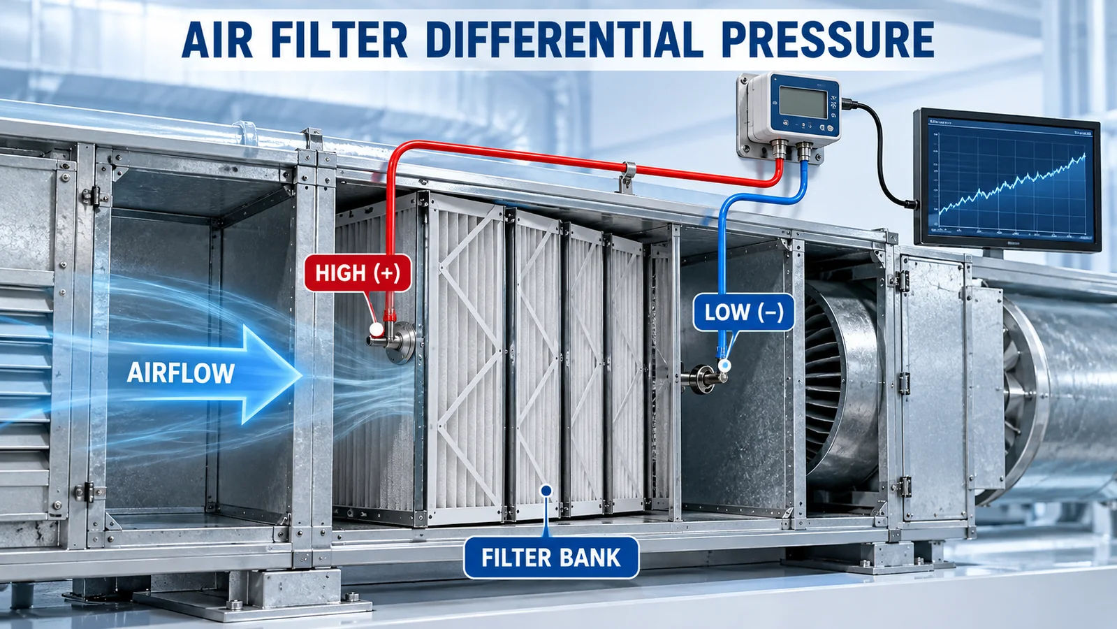
An air filter differential pressure sensor measures the static-pressure difference between the upstream and downstream sides of a filter bank. As the filter loads with particles, its resistance to airflow usually rises, so pressure drop can support condition-based maintenance and a building-automation alarm.
The correct measurement is not “duct pressure near the filter.” It is:
filter ΔP = upstream static pressure − downstream static pressure
That value is meaningful only with the filter model, airflow, fan state and installation condition. Set changeout criteria from the filter manufacturer’s rated final resistance and the system design—not from one universal pressure threshold.
What Does Filter Differential Pressure Tell You?
Pressure drop is the resistance the installed filter assembly presents to airflow. A new clean filter has an initial resistance at a stated airflow. Dust loading, moisture, damage, airflow change, rack leakage and filter geometry can change the measured value.
An upward trend at similar airflow commonly indicates loading. However, differential pressure does not directly prove filtration efficiency or particle removal. A missing filter or bypass leak may produce a low drop while allowing contaminants through. A wet filter can create a rapid high drop even if its dust loading is moderate.
Filter drop is different from duct static pressure
A supply-duct static sensor normally compares one duct location with a reference space for fan control. A filter sensor compares two points on opposite sides of the same filter bank. The duct static-pressure placement guide explains why these measurements require different tap locations and references.
Where Should the High and Low Pressure Taps Go?
Connect the upstream static-pressure tap to the sensor’s HIGH (+) port and the downstream tap to LOW (−) when a positive pressure-drop reading is desired. The taps should represent the static pressure immediately before and after the complete filter bank without being dominated by local turbulence.
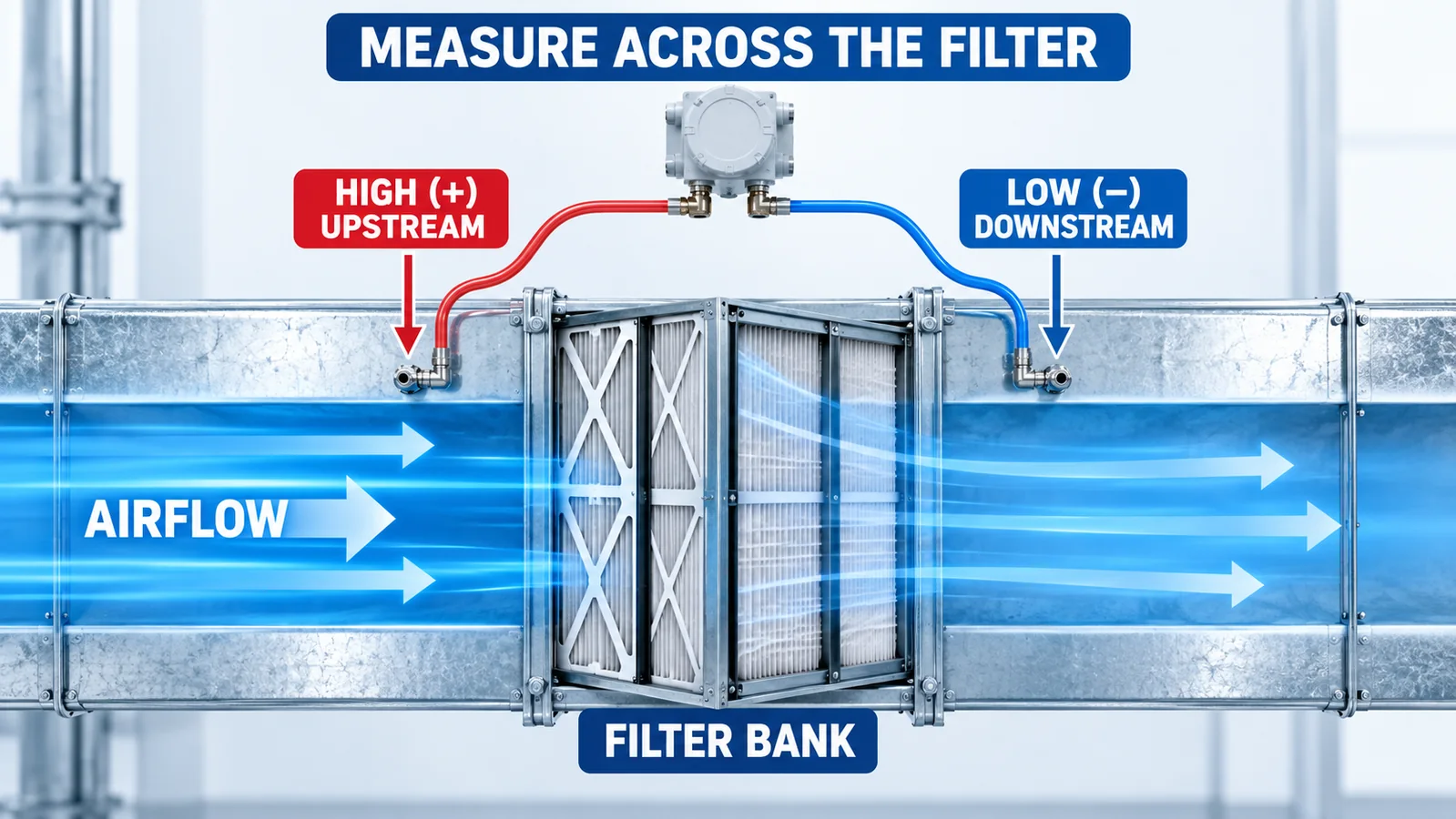
Use a proper static tap or manufacturer-approved pickup. A tube opening that faces into the airflow can sense impact effects and overstate static pressure. Avoid placing a tap in the immediate wake of a fan, elbow, damper, abrupt transition or obstruction unless the equipment design has a validated measurement location.
Define what the measurement includes
If the taps span only the filter media, the reading excludes a prefilter, grille or coil. If they span an entire filter housing, the reading may include rack and transition losses. Document the measurement boundary so the baseline and alarm have the same meaning after maintenance.
For multiple filter banks in series, individual monitoring is more diagnostic than one pair of taps around everything. A high combined drop cannot identify which stage needs service. If only one sensor is possible, document the limitation and use inspection or temporary measurements during troubleshooting.
Why Does Filter Pressure Drop Change with Airflow?
Pressure drop increases with airflow through a given filter and installation. Therefore, a variable-air-volume system can show a changing filter differential even when the filter loading has not changed.
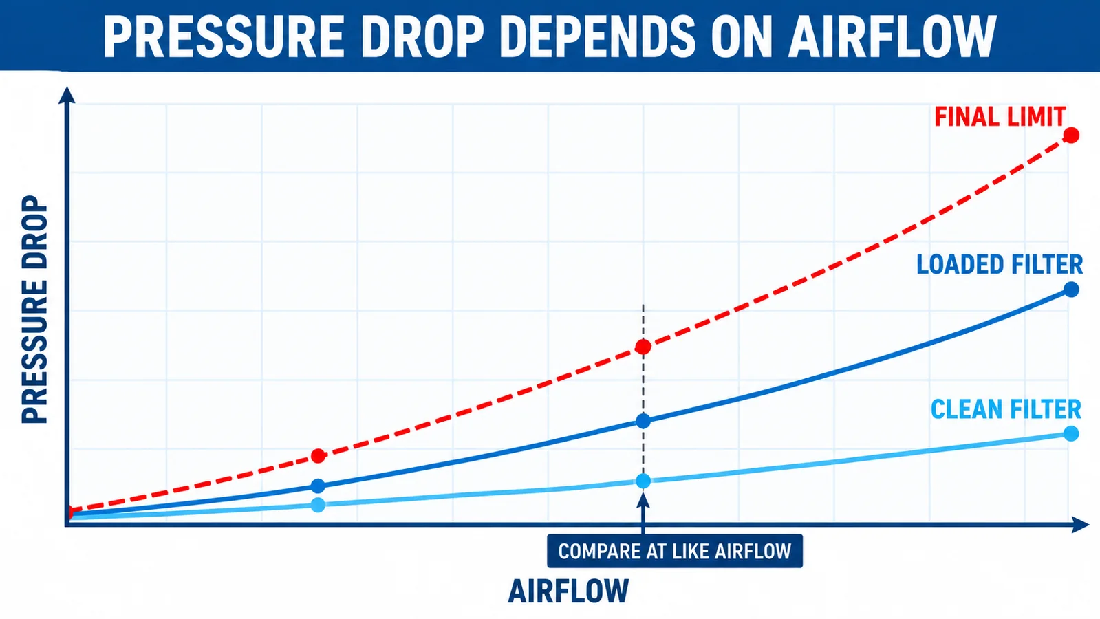
A useful trend should compare like operating states. Options include:
- recording the clean-filter baseline at several airflow points;
- trending differential pressure together with airflow or fan speed;
- evaluating only when the fan is proven on and airflow is inside a defined band;
- applying a validated normalization model supplied by the equipment designer;
- using separate operating-mode thresholds when the AHU has distinct stable modes.
Do not divide by fan speed or square airflow automatically. The relationship depends on the filter, rack, system and control behavior. Validate any normalization against measured clean and loaded performance.
Face velocity matters
The same total airflow through a smaller effective filter area creates higher face velocity and usually higher pressure drop. A replacement filter with different dimensions, media area or construction can change the baseline even if its efficiency class looks similar. Record the exact filter model, dimensions, quantity and installed orientation.
What Are Initial and Final Resistance?
The public ANSI/ASHRAE Standard 52.2 document defines initial resistance as the pressure loss of the clean device at a specified airflow. It defines rated final resistance as the operating pressure loss at the airflow rate where the manufacturer recommends replacement or renewal.
That language matters: the value is tied to a stated airflow and manufacturer recommendation. A number from another filter, a lab test at another flow or a generic internet chart is not a safe changeout threshold for the installed system.
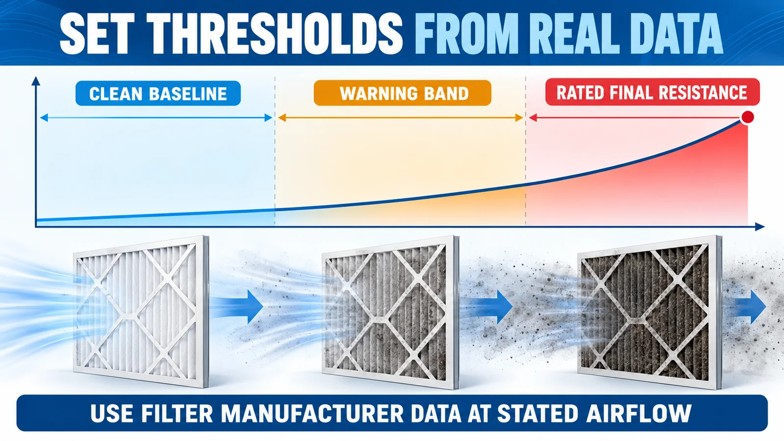
Build a three-level maintenance strategy
- Clean baseline: record pressure drop after correct filter installation at known operating states.
- Warning band: create a service-soon threshold below the approved final limit so maintenance can be scheduled.
- Changeout or action limit: use the filter manufacturer’s rated final resistance or a lower project-specific limit established by the designer, owner or equipment manufacturer.
Also define low-drop and sensor-fault logic. Monitoring only a high threshold misses bypass, missing media, disconnected tubing and fan-off conditions.
Pressure drop is not the only replacement criterion
Critical filters may require scheduled replacement, integrity testing, particle monitoring, visual inspection or application-specific procedures in addition to differential pressure. Moisture, biological contamination, hazardous dust or damaged media can require action before a final resistance is reached. Follow the filter and facility requirements.
How Do You Select the Sensor Range?
Start with measured and manufacturer data:
- clean pressure drop at minimum, normal and maximum airflow;
- expected warning and final resistance;
- possible negative or reverse flow;
- startup and shutdown transients;
- maximum common-mode pressure at each port;
- credible differential overpressure if one tube is blocked or disconnected.
Choose the narrowest practical range that covers the validated measurement envelope and required margin without sacrificing overload safety. A 10 kPa full-scale sensor can display a 150 Pa filter drop, but a %FS accuracy specification may make the error too large for useful maintenance discrimination.
. przewodnik dotyczący dokładności pełnej skali w porównaniu z odczytem shows why range selection affects real engineering-unit error.
Example range exercise
Suppose an AHU’s approved filter data and commissioning measurements show:
- clean drop near 90 Pa at normal airflow;
- project warning at 180 Pa;
- approved action limit at 250 Pa;
- maximum expected measurement during normal modes at 300 Pa.
A unidirectional 0–500 Pa range might be evaluated, subject to accuracy, overload, temperature and availability. A ±500 Pa range might be preferred if reverse flow or signed diagnostics matter. These values are an illustrative selection exercise, not universal HVAC thresholds.
What Accuracy and Performance Specifications Matter?
| Specyfikacja | Filter-monitoring relevance |
|---|---|
| Accuracy across temperature | Determines confidence in clean-to-warning separation |
| Zero offset and drift | Low-range measurements can be dominated by zero error |
| Resolution and noise | Affect trend stability and alarm chatter |
| Response/filtering | Must reject turbulence without hiding real changes |
| Differential overpressure | Protects the element during faults or service |
| Common-mode pressure | Each port may see substantial duct pressure despite small ΔP |
| Medium compatibility | Air may contain humidity, condensate, dust or chemicals |
| Wyjście/interfejs | Must match OEM PCB or field/BAS input |
| Calibration/zero method | Supports commissioning and maintenance checks |
Do not confuse digital resolution with accuracy. A 24-bit ADC can provide fine output codes while the complete sensor accuracy remains limited by offset, drift and calibration.
How Should the Tubing Be Installed?
Tubing is part of the measurement system. A leak on the high side usually lowers the reading; a blocked or wet line can create slow, biased or frozen values.
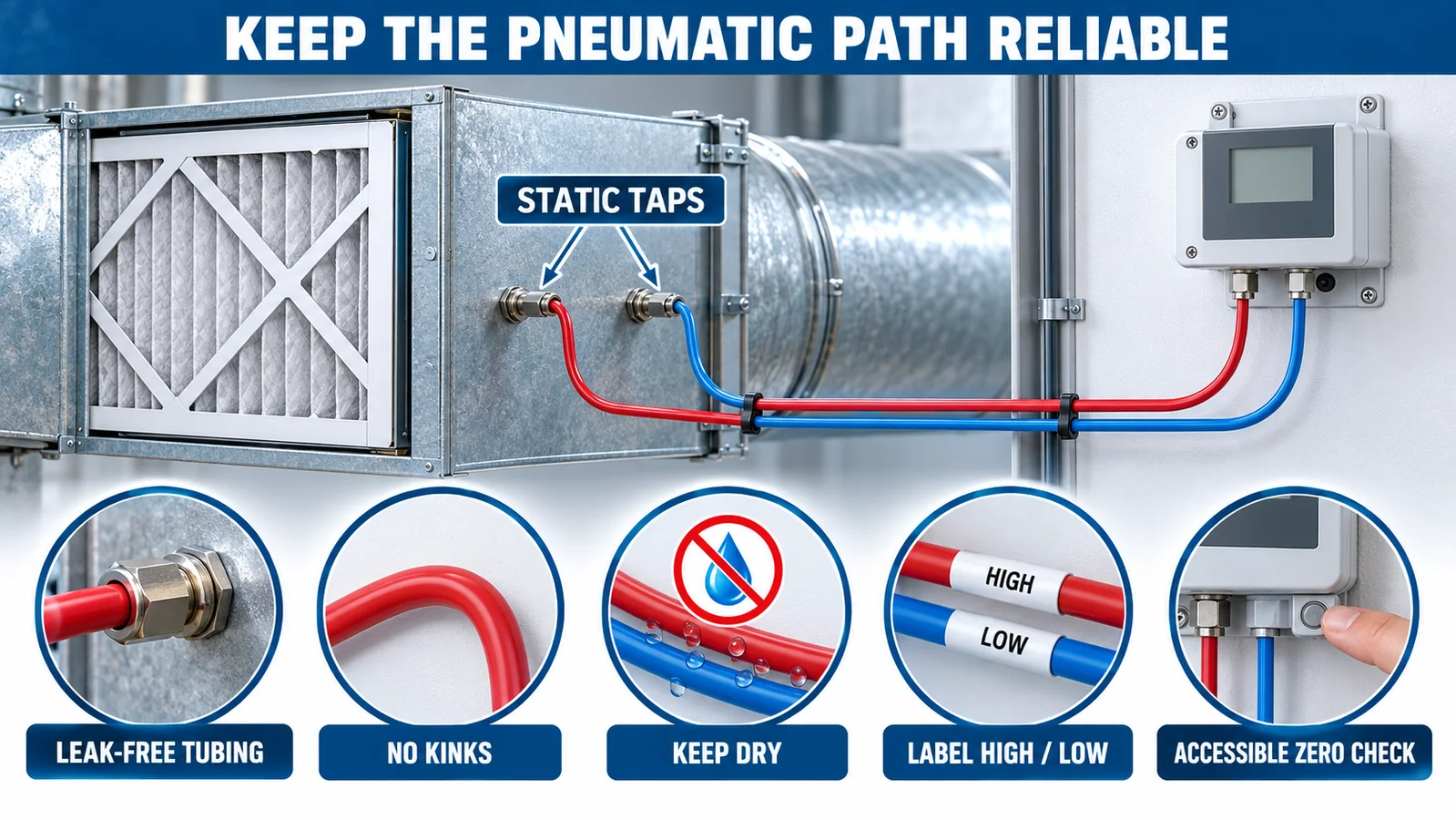
Use tubing compatible with the air conditions and port fittings. Keep runs protected, supported and free of kinks. Avoid low points where condensate can collect, or provide an approved drain arrangement. Keep both high and low runs reasonably similar when temperature gradients could matter.
Label HIGH I LOW at the taps, sensor and drawings. Make the sensor accessible for a zero check and reference comparison. Protect open reference or pressure ports during construction so dust does not enter before the system is commissioned.
Should the sensor be zeroed with both ports open?
Follow the exact sensor instruction. A common field check equalizes both ports so the true differential is zero, then observes or adjusts the zero. Do not disconnect tubes on a running or contaminated system without a safe procedure. A zero adjustment should not be used to hide asymmetric tubing, a blocked tap or unintended cabinet pressure.
How Should BAS Alarm Logic Work?
A robust BAS point uses context, not a single comparison:
- fan proven on;
- airflow or fan-speed operating band;
- differential pressure and rate of change;
- time delay or persistence;
- maintenance-reset and filter-change event;
- low, high and sensor-fault limits;
- fallback behavior if the signal is unavailable.
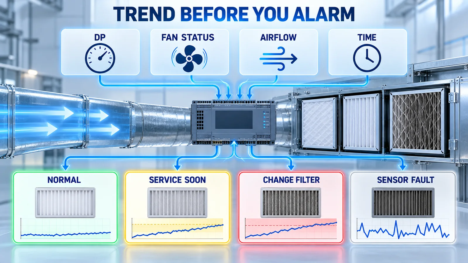
Example states
| State | Conditions to investigate | Action concept |
|---|---|---|
| Fan off | DP near zero expected | Suppress normal dirty-filter alarm; check implausible nonzero value |
| Normal | DP inside flow-aware baseline band | Trend |
| Service soon | Persistent rise toward approved limit | Create maintenance notification |
| Change filter/action | Approved final or project limit reached | Execute facility procedure |
| Abnormally low | Fan on but DP below expected band | Check airflow, bypass, missing filter, taps and tubing |
| Signal fault | Out-of-range, frozen, disconnected or diagnostic flag | Inspect measurement path; do not infer filter condition |
Use hysteresis and persistence to prevent alarm chatter. After a filter change, record the new clean baseline at the same operating condition. If the baseline differs materially, inspect filter model, orientation, seals, rack bypass, airflow and sensor zero before accepting it.
How Do You Commission the System?
- Verify filter model, orientation, quantity and rack sealing.
- Verify tap locations and measurement boundary.
- Check high/low tubing, fittings, labels and condensate path.
- Equalize or follow the approved sensor zero procedure.
- Compare the installed sensor with a calibrated differential reference at the same taps.
- Verify engineering units and controller scaling.
- Record clean pressure drop at defined airflow points.
- Simulate or temporarily apply alarm values through an approved test method.
- Verify BAS text, priority, delay, hysteresis and notification routing.
- Save the as-left data, filter details and next maintenance action.
A handheld reading taken at different taps is not a valid comparison. Use the same high and low reference points or quantify the expected difference.
What Do High, Low and Unstable Readings Mean?
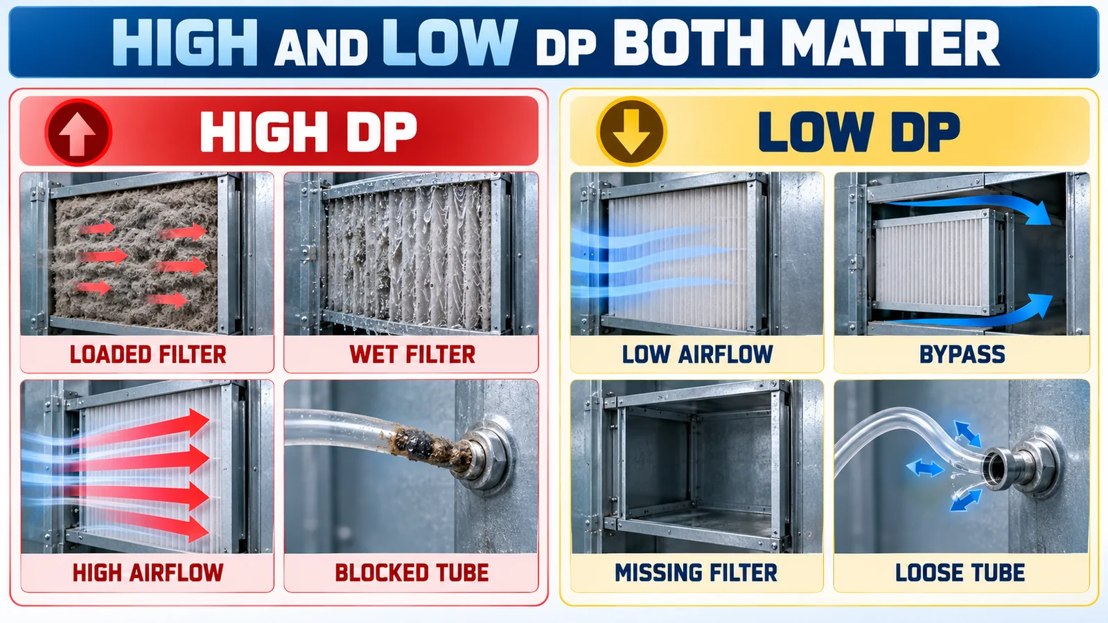
| Objaw | Check measurement path first | Then inspect the system |
|---|---|---|
| High DP | Blocked low tube, reversed/scaled signal, water in line, zero error | Loaded/wet filter, excessive airflow, wrong filter, obstructed rack |
| Low DP | Loose high tube, blocked high tap, fan-off logic, wrong range | Low airflow, bypass, missing/damaged filter, open access door |
| DP jumps | Loose tubing, turbulent tap, condensate movement, electrical noise | Fan hunting, damper changes, rapidly changing airflow |
| DP does not change after replacement | Frozen value, blocked lines, wrong BAS point | Replacement not in monitored bank, unchanged airflow or installation issue |
| Baseline gradually shifts at constant flow | Sensor zero/drift, tubing contamination | Rack leakage, filter deformation or system change |
Pressure drop is a diagnostic signal, not a verdict. Confirm airflow and inspect the physical filter before deciding the cause.
Where Does Winsen WPAS13 Fit?
The official WPAS13 product page describes a board-level MEMS differential-pressure gas sensor with dual nozzles, digital compensation, a 24-bit ADC and I²C output. Published ranges include ±0.5 kPa, ±1 kPa, ±2 kPa and wider options, plus optional unidirectional low ranges. The page lists ±1%FS accuracy and a −5 to 65°C working-temperature range.
Those low ranges can be relevant to embedded AHU or equipment-level filter monitoring. However, WPAS13 is not a finished wall-mounted or duct-mounted BAS transmitter. The OEM must provide PCB integration, protected tubing, enclosure, power, I²C communication, environmental protection, calibration/zero handling and any field-facing output or protocol.
Request the current variant datasheet, differential overpressure, common-mode limits, gas/condensation restrictions, port geometry and accuracy conditions before design release.
Where Does Winsen WPAK67 Fit?
The official WPAK67 page I manual describe a stainless-steel isolation-film differential pressure core with a raw millivolt bridge output. The published family range begins around 10 kPa, substantially higher than the few-hundred-pascal range common in many HVAC filter applications.
Therefore, WPAK67 is normally not the first range choice for ordinary low-pressure air-filter monitoring. It may be evaluated for higher-differential industrial filtration or another OEM application where its structure, media compatibility and range match the process. The OEM must add excitation, amplification, compensation, packaging and calibration. Do not select it only because “differential pressure” appears on the datasheet.
. sensor-core-versus-transmitter guide explains these integration levels.
What Should an OEM or AHU RFQ Include?
Send the following application data:
- filter manufacturer, model, efficiency class, size and quantity;
- rated airflow and operating airflow range;
- clean initial resistance and rated final resistance curves;
- tap locations and whether multiple banks need separate monitoring;
- desired range, sign, accuracy, resolution and alarm response;
- differential and common-mode overpressure scenarios;
- temperature, humidity, dust and condensation exposure;
- tubing length, port and enclosure arrangement;
- PCB-level I²C, analog voltage, current loop or BAS protocol requirement;
- calibration, traceability, EMC and service strategy.
Skontaktuj się z Winsenem with that envelope to review the appropriate current differential-pressure sensing option rather than starting with a model number alone.
Często zadawane pytania
What is a normal pressure drop across an HVAC filter?
There is no universal value. It depends on the exact filter, size, airflow, loading and installation. Use manufacturer data and record the clean installed baseline at stated airflow.
Which port connects upstream of the filter?
For a positive filter-drop reading, connect the upstream static tap to HIGH (+) and the downstream tap to LOW (−). Verify the specific sensor documentation and BAS sign convention.
Does high differential pressure always mean a dirty filter?
No. High airflow, a wet or incorrect filter, blocked tubing, water in a line or scaling error can also produce a high reading. Verify the measurement path and airflow before replacing the filter.
Can low pressure drop indicate a problem?
Yes. Low DP with the fan running can indicate low airflow, bypass, a missing or damaged filter, an open access door, disconnected tubing or a blocked upstream tap.
Can a differential pressure sensor measure airflow?
Not from filter drop alone. Airflow can be inferred only with a calibrated relationship for the complete flow element/system and operating conditions. A filter is not automatically a calibrated flow station.
Should the dirty-filter alarm be active when the fan is off?
Normally the logic should consider fan status and airflow state. With the fan off, filter DP should be near zero; a nonzero value may support a sensor/tubing diagnostic rather than a dirty-filter alarm.
Make Filter Maintenance Evidence-Based
Reliable filter monitoring combines correct static taps, leak-free tubing, an appropriately ranged sensor, a clean baseline, manufacturer-rated final resistance and BAS logic that understands airflow and fan state. That system can reduce premature replacement while catching loading, bypass and measurement faults that a calendar alone may miss.
