Piezoresistive Sensors: Complete Guide for Pressure & Strain Measurement
Piezoresistive sensors convert mechanical stress/strain into an electrical resistance change. They are widely used in pressure sensors, load/force sensors, and MEMS devices because they’re compact, sensitive, easy to interface (bridge output), and scalable for mass production. A well-cited review notes piezoresistive sensors were among the earliest micromachined silicon devices and helped drive early MEMS development.
What is the piezoresistive effect?
The piezoresistive effect is the change in a material’s electrical resistivity (and therefore resistance) when mechanical stress is applied. In metals, resistance change is dominated more by geometry (length/area change). In semiconductors (like doped silicon), resistivity change can dominate—making the effect much stronger and enabling high sensitivity.
How piezoresistive sensors work (core equations)
1) Strain → resistance change
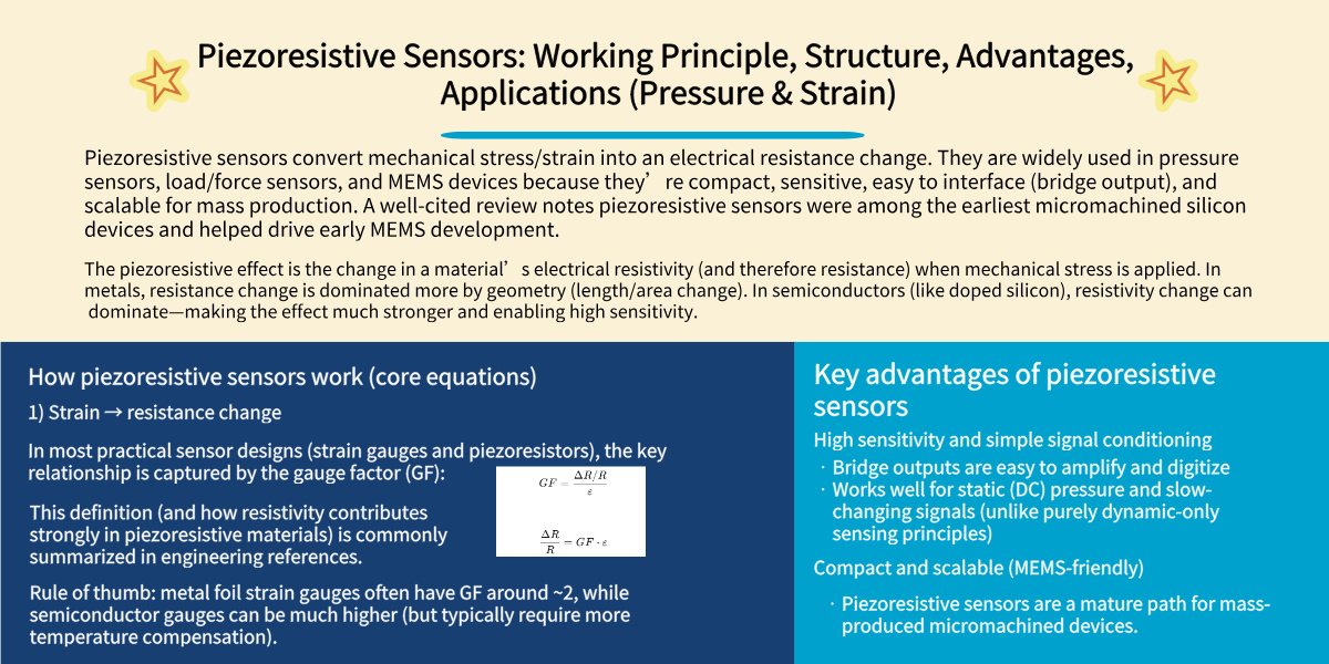
In most practical sensor designs (strain gauges and piezoresistors), the key relationship is captured by the gauge factor (GF):

This definition (and how resistivity contributes strongly in piezoresistive materials) is commonly summarized in engineering references.
Rule of thumb: metal foil strain gauges often have GF around ~2, while semiconductor gauges can be much higher (but typically require more temperature compensation).
2) Resistance change → voltage output (Wheatstone bridge)
Most piezoresistive sensors place resistors in a Wheatstone bridge so small resistance changes become a measurable voltage signal. Bridge analysis and full/half-bridge configurations are standard for piezoresistive sensing.
Why the bridge matters
- Improves sensitivity (mV/V output)
- Rejects common-mode effects
- Makes temperature compensation easier (with matched resistors)
Typical structure of a piezoresistive pressure sensor (MEMS)
A classic MEMS piezoresistive pressure sensor includes:
- A thin diaphragm (silicon) that deflects under pressure
- Piezoresistors placed in high-stress regions of the diaphragm
- A Wheatstone bridge that outputs a voltage proportional to pressure
Modern MEMS analyses describe how diaphragm deflection and stress translate into bridge output voltage (often modeled analytically and with FEA).
Materials used in piezoresistive sensors
Silicon (single-crystal / polysilicon)
- Dominant in MEMS pressure sensors and micro strain sensors
- Strong piezoresistive response, especially depending on crystal orientation and doping
- Extensively studied for piezoresistive coefficients and their dependence on material conditions
Metal foil / thin-film resistors
- Common in classic strain gauges and load cells
- Lower sensitivity than silicon piezoresistors but often excellent stability (with proper compensation)
Wide bandgap (high-temperature) piezoresistive materials (e.g., SiC)
For harsh environments, research shows piezoresistive pressure sensors based on materials like SiC can target very high temperature ranges (hundreds of °C) with specialized packaging.
Key advantages of piezoresistive sensors
High sensitivity and simple signal conditioning
- Bridge outputs are easy to amplify and digitize
- Works well for static (DC) pressure and slow-changing signals (unlike purely dynamic-only sensing principles)
Compact and scalable (MEMS-friendly)
Piezoresistive sensors are a mature path for mass-produced micromachined devices.
Broad application coverage
Piezoresistive pressure sensors are commonly offered in absolute, gauge, and differential configurations depending on the pressure reference needed.
Winsen pressure sensor
Limitations and engineering challenges
Temperature effects and drift
Resistance depends on temperature, and silicon piezoresistive coefficients can also vary with temperature—so real products typically use:
- temperature compensation (analog or digital)
- calibration across temperature points
- matched bridge resistors and packaging strategies
Bridge/gauge factor teaching notes also emphasize temperature terms can appear in real measurements.
Packaging & media isolation
In pressure sensing, the mechanical stack (diaphragm, gel/oil fill, isolating membrane) can dominate:
- long-term stability
- hysteresis
- overload behavior
Your sensor choice should consider media compatibility, sealing, and mechanical fatigue.
Stress concentration and placement sensitivity
Research on MEMS strain sensors shows geometry features (trenches/stress concentration regions) can strongly affect sensitivity—great for performance, but it also makes design and process control important.
Piezoresistive vs capacitive vs piezoelectric (quick comparison)
| Principle | Best at | Typical strengths | Common tradeoffs |
|---|---|---|---|
| Piezoresistive | Static + dynamic pressure/strain | Simple interface, compact, strong output | Temp drift, needs compensation |
| Capacitive | Low pressure, high resolution | Very low power, low drift potential | Parasitics, packaging sensitivity |
| Piezoelectric | Dynamic events (vibration/impact) | Excellent dynamic response | Not ideal for true DC/static measurement (depends on design) |
(For force measurement, many industry comparisons focus on strain-gauge vs piezoelectric tradeoffs.)
Common applications
Pressure sensing (most common)
- HVAC pressure monitoring, pneumatic systems
- hydraulics (with suitable range/overpressure)
- vacuum/absolute pressure measurement (absolute sensors)
- differential pressure for filters, ducts, cleanrooms
Force / load / torque sensing
- load cells (often strain-gauge based, sometimes semiconductor in special cases)
- structural monitoring and test rigs
Automotive and industrial control
- manifold/boost pressure, oil pressure, process pressure transmitters
- compact embedded modules in equipment
How to specify a piezoresistive sensor correctly (buyer checklist)
When writing a datasheet requirement or RFQ, include:
- Pressure type: absolute / gauge / differential
- Range + overload: working range, proof, burst
- Media: dry gas / water / oil / refrigerant / corrosive
- Accuracy definition: %FS vs %reading, include temp effects
- Temperature range: operating + compensated range
- Output & interface: mV/V bridge, amplified voltage, 4–20 mA, I²C/SPI, etc.
- Mechanical: port/thread, sealing, mounting stress limits
- Long-term stability: drift/year, hysteresis, repeatability
FAQs
Are piezoresistive sensors the same as strain gauges?
Piezoresistive sensing is the principle (resistance change with stress/strain). Many strain gauges use that idea; silicon piezoresistive sensors are essentially high-sensitivity strain sensing integrated into MEMS structures.
Why do piezoresistive sensors use a Wheatstone bridge?
Because it converts tiny resistance changes into a stable voltage output and supports compensation and sensitivity improvements.
Can piezoresistive pressure sensors measure static pressure?
Yes—this is a key advantage versus purely dynamic-only sensing approaches. Piezoresistive pressure sensors are widely used for steady pressures as well as changing pressures.
What’s the biggest weakness of piezoresistive sensors?
Temperature dependence (offset/span drift) is the most common engineering challenge—usually handled by calibration and compensation.
Are piezoresistive sensors used in MEMS?
Yes—piezoresistive sensors are historically important in micromachined silicon devices and remain widely used in MEMS pressure sensors.


