
When a pressure transducer reads wrong at zero, verify the pressure at its sensing port and check the signal independently of the display. Many apparent zero errors come from an absolute sensor exposed to atmosphere, pressure trapped behind a valve, a wet impulse line, an obstructed gauge vent, or a controller scaled for a different range. A zero adjustment is appropriate only after the reference condition, installation and output have been checked and the ordered device supports the adjustment.
Start with three observations taken at the same time: the reference pressure, the raw transmitter output and the value displayed by the controller. Record the pressure reference and engineering units alongside each observation. This short record usually narrows the fault to the pressure path, the transducer or the receiving system before any part is replaced.
What Does Zero Mean for This Transducer?
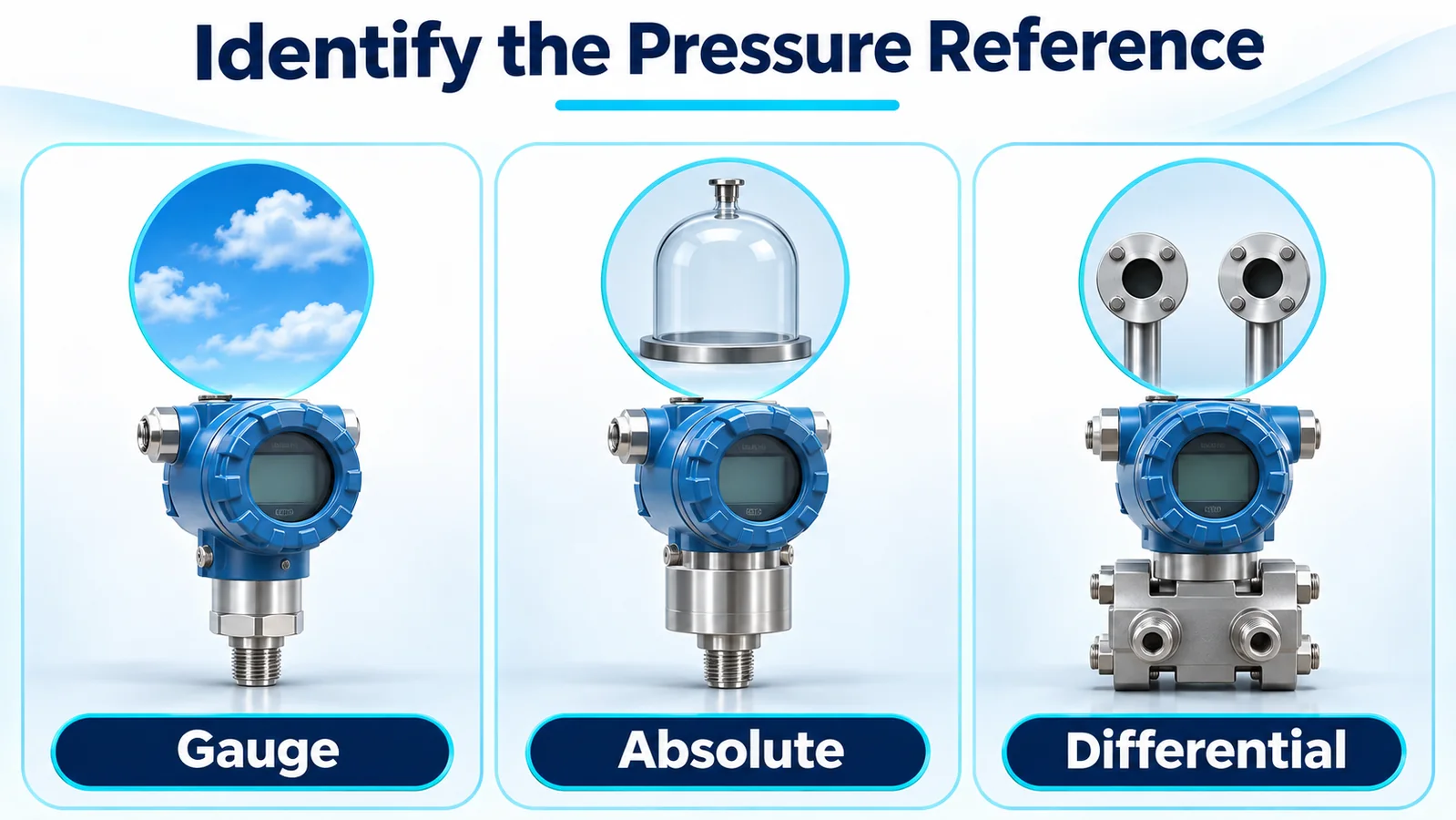
| ಉಲ್ಲೇಖ | Condition that represents zero | What to check in the field |
|---|---|---|
| Vented gauge | Process port and atmospheric reference see the same local pressure | Confirm local atmosphere reaches the reference vent and the process side is actually at that pressure |
| ಸಂಪೂರ್ಣ | A vacuum reference of zero absolute pressure | An open port normally reports local atmospheric pressure in absolute units |
| ಮೊಹರು ಗೇಜ್ | Pressure equals the device’s sealed reference | Expect a possible difference from local atmospheric pressure and consult the model documentation |
| ಭೇದಾತ್ಮಕ | High and low ports see the same pressure | Establish equal pressure through the approved manifold procedure and account for unequal liquid heads |
A compound gauge range illustrates why the physical zero and electrical lower endpoint must be treated separately. An ideal 4–20 mA transmitter ranged from −1 to +3 bar gauge produces 8 mA at 0 bar gauge. Four milliamps represents −1 bar in this example. If the readout interprets 4 mA as 0 bar, it shows an offset even when the transmitter is working exactly as configured.
Look for the reference designation on the nameplate, order code or calibration record. Do the same for the configured lower and upper range values. A spare with the same connector and thread may have a different pressure reference, transfer curve or range. Document the exact variant before using a replacement as a diagnostic comparison.
Is the Sensing Port Really at Zero?
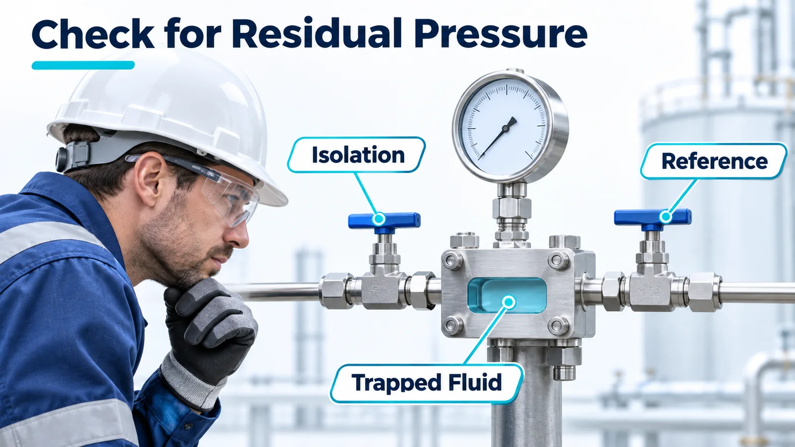
An upstream gauge can read zero while a closed isolation valve leaves pressure trapped in the transmitter cavity or impulse tube. A regulator, check valve, clogged snubber or viscous residue can also prevent pressure at the port from following the main pipe. A pressure reading that decays slowly after shutdown suggests a trapped or restricted path. Record how long it takes to settle and compare it with a reference on the same hydraulic node.
Only use the equipment’s approved isolation and depressurization procedure. Confirm the condition at the authorized test point with suitable reference equipment. Avoid assuming that a running pump has stopped delivering pressure or that a remote indication proves a local connection can be opened. For hazardous or hot media, use the applicable service procedure and qualified personnel.
A wet line can generate a repeatable static offset even when the vessel is empty. A 0.5 m vertical column of water produces about 4.9 kPa of head, using an illustrative density of 1,000 kg/m³ and standard gravity. Whether it adds to or subtracts from the indicated value depends on the transmitter elevation and the process arrangement. An offset of this size is only a few percent of many pressure spans but could consume a large share of a low-range instrument’s usable output.
For a differential measurement, check the legs individually. Two taps connected to a common vessel may see different hydrostatic heads if one leg has condensate or if liquid levels differ. Equalizing pressure directly at the transmitter establishes the sensing element’s response under a known condition. The installed result still depends on the impulse lines and their fill.
Does the Error Appear in the Raw Signal or Only on the Screen?

Use a suitable current meter, voltage measurement or supported digital readout for the ordered output. Observe the raw value without changing the configuration. For a linear 0–10 bar gauge loop, 4.00 mA corresponds to 0 bar and 20.00 mA corresponds to 10 bar. If the transmitter delivers 4.00 mA at verified zero but a controller shows 0.4 bar, inspect the controller’s configured input, scaling, offset and engineering units. The two-wire pressure transmitter wiring guide explains loop supply and analog input checks.
If the independent meter sees 4.24 mA at known zero on the same 0–10 bar range, the output corresponds to 0.15 bar. Check one or more higher reference points before attributing the full error to a sensor shift. A similar equivalent error at several pressures suggests an offset. A reading that moves farther from the expected value with pressure suggests another contribution such as gain, configured span or nonlinearity.
For a voltage output, confirm the meter uses the intended signal reference. A difference in common potential or an incompatible input can distort the receiving value. For a ratio-based signal, use the actual excitation when calculating the expected output. For digital output, confirm the register, byte order, units and stale-data handling in the device documentation. In each case, compare the device signal with what the receiving system claims it received.
What Installation Conditions Can Shift the Reading?
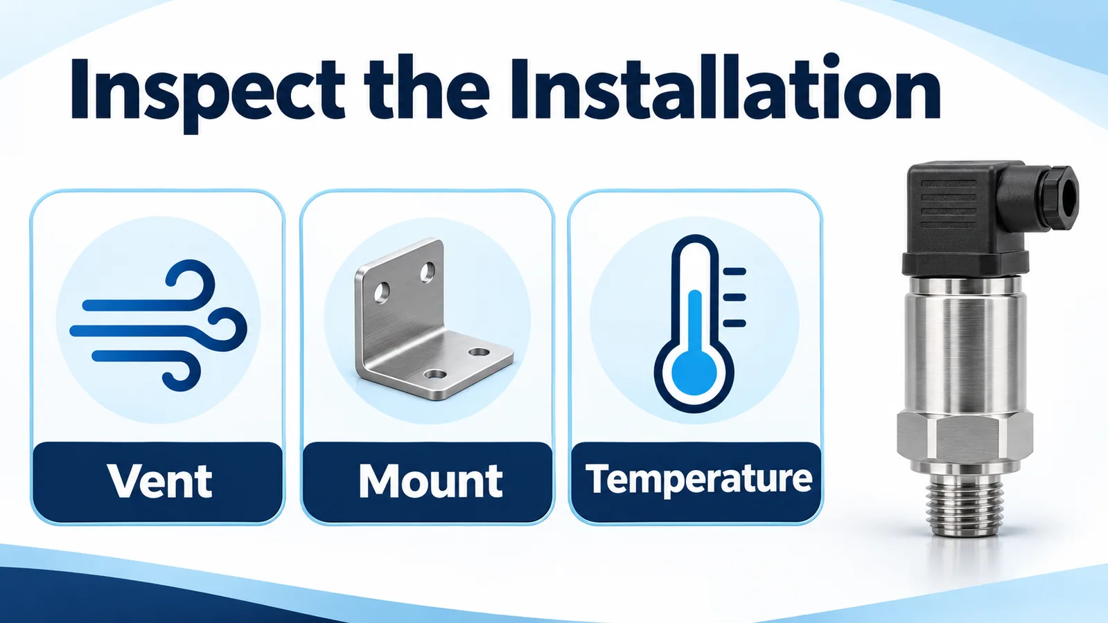
Gauge vent. Moisture, adhesive, dirt, paint or a sealed cable termination can impair an atmospheric reference. Inspect only the external parts described in the manual. A vent that has been flooded may require service rather than cleaning in place. Check whether the cable, connector or housing carries the atmospheric reference before altering its routing.
Mechanical mounting. The housing or sensing element can be strained by overtorque, a mismatched fitting, misaligned rigid tubing or a seal loaded outside its designed seat. Compare the installed reading with a controlled bench reading after proper removal. An offset that returns whenever the transmitter is installed points to the assembly or pressure path. The ಒತ್ತಡ ಸಂವೇದಕ ಅನುಸ್ಥಾಪನ ಮಾರ್ಗದರ್ಶಿ covers thread, seal and mounting checks.
Temperature and warm-up. Record ambient and process temperatures together with time since power-up. An error that appears at startup and settles may reflect temperature equilibration or electronics warm-up. An error that tracks temperature throughout operation belongs in the installed error budget. Use a repeated reference check at stable conditions to distinguish a thermal trend from a lasting offset after an overload.
Pressure events and handling. Review pump trips, rapid valve events, cleaning cycles and maintenance history. A new offset after a pressure excursion can indicate permanent damage, especially when the span or repeatability has also changed. Compare the event with the exact overload specification and preserve the as-found condition before adjustment. For liquid-line transients, see the water hammer protection guide.
What Should an As-Found Record Contain?

Capture the serial number, ordered output, expected range mapping, pressure reference, mounting position, test instrument and date. Include whether the transmitter was connected to the PLC, how the verified pressure was established, and which raw value and display value were observed. Add a photo of the port orientation or test arrangement if it helps another technician reproduce the observation.
Record repeated measurements at the lower point when the reference is stable. Note any drift after an up-and-down pressure cycle. A reading that fails to return to the same value after a cycle is different evidence from a steady offset observed immediately after power-up. Check for leakage, trapped media or pressure source instability before interpreting the difference as sensor hysteresis.
Use the application’s acceptable limit in engineering units. For instance, a ±0.5% full-scale specification on a 10 bar span corresponds to ±0.05 bar for that specified term. Reference uncertainty, temperature and receiving-system errors may contribute separately. Apply the applicable acceptance method before passing or failing the assembled loop. See the full-scale and reading error guide for how the units are calculated.
When Should You Trim, Reconfigure or Replace It?
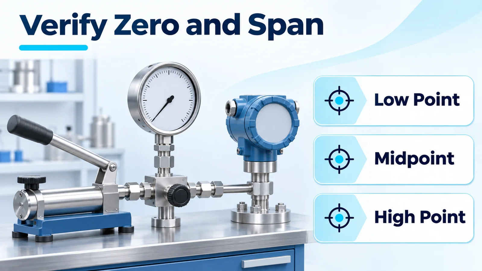
If the output is correct and only the screen disagrees, correct the scaling or input configuration and verify the complete channel. If the pressure at the port differs from what the operator expected, resolve the isolation, trapped liquid, elevation or reference issue. A repeatable offset at a known reference can justify a supported adjustment when the procedure and application limits allow it.
Distinguish zero trim, analog output trim and range configuration. A sensor trim changes how the device interprets the reference pressure. Output trim addresses disagreement between commanded and actual analog output on a device that supports it. Ranging changes which pressures correspond to the output endpoints. These operations affect different parts of the measurement chain. The Fluke pressure transmitter calibration guide illustrates separate input and output checks on a HART example.
After any approved adjustment, check the lower, midpoint and upper points that are safe for the configuration. Include descending measurements where the procedure calls for them. Save the as-left values and confirm the controller matches the independent observation. If accuracy cannot be restored, the output is unstable, or the measured span changes unexpectedly, follow the equipment owner’s repair or replacement decision. Preserve evidence of possible overload even if a superficial offset could be removed.
How Do WPCK07 and WPCH04 Fit Into the Check?
ಯ ೦ ದನು ವಿನ್ಸೆನ್ WPCK07 is a diffused-silicon transmitter family with several pressure references and electrical outputs, including a current-loop variant. Set the expected zero signal from the ordered reference and output. A unit with voltage or digital output needs a different check from a two-wire current-loop unit.
ಯ ೦ ದನು WPCH04 is a conditioned ceramic pressure transmitter offered with multiple output and supply configurations. Compare the voltage or current measured at its specified electrical interface with the expected transfer for the part supplied. Neither family name alone identifies a field trim procedure. Ask for the current datasheet and calibration instructions for the specific configuration.
FAQ
Why does a transducer show about 1 bar when the port is open?
An absolute instrument at local atmospheric pressure commonly reports a value around 1 bar absolute. Weather and elevation affect the actual reading. Confirm the nameplate and compare with a suitable local reference before interpreting the result as a fault.
Why is my 4–20 mA sensor showing a negative pressure at rest?
Check the lower range value, loop current and controller scaling. A small under-range reading can also come from an offset, thermal influence or wiring and input problems. Use the product’s specified fault behavior to interpret a reading outside the nominal loop range.
Can I correct an offset with a PLC bias?
A documented installed offset may be handled in the controller if that is part of the measurement design and the reference validation supports it. Keep the raw measurement available and verify the correction over the working range. A bias can hide trapped pressure, damaged hardware or a wrong configuration if applied without diagnosis.
What should I send to Winsen for troubleshooting?
Send the model code and serial number, pressure reference, configured range, output type, raw signal, controller reading and reference value at two or more known pressures. Include recent temperature, installation and pressure events. For a pressure transducer zero reading problem, that information lets Winsen technical support review the actual measurement chain.
