Capacitive and piezoresistive sensing are the two most common cores behind modern pressure transducers (including MEMS). On a quiet bench, both can look “good enough.” In the field, their differences show up quickly—especially with temperature swings, low-pressure differential measurements, EMI/parasitics, overpressure events, and power budget limits.

Both technologies can be implemented as absolute, gauge, or differential pressure sensors.

1) How each technology works

Piezoresistive pressure sensors

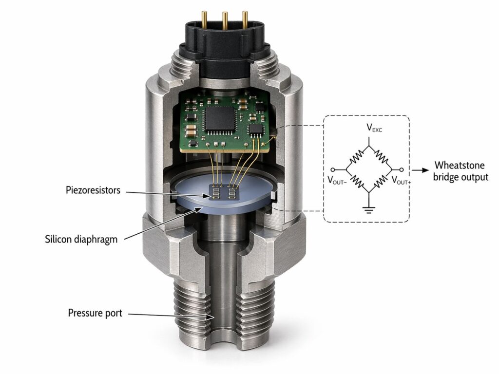
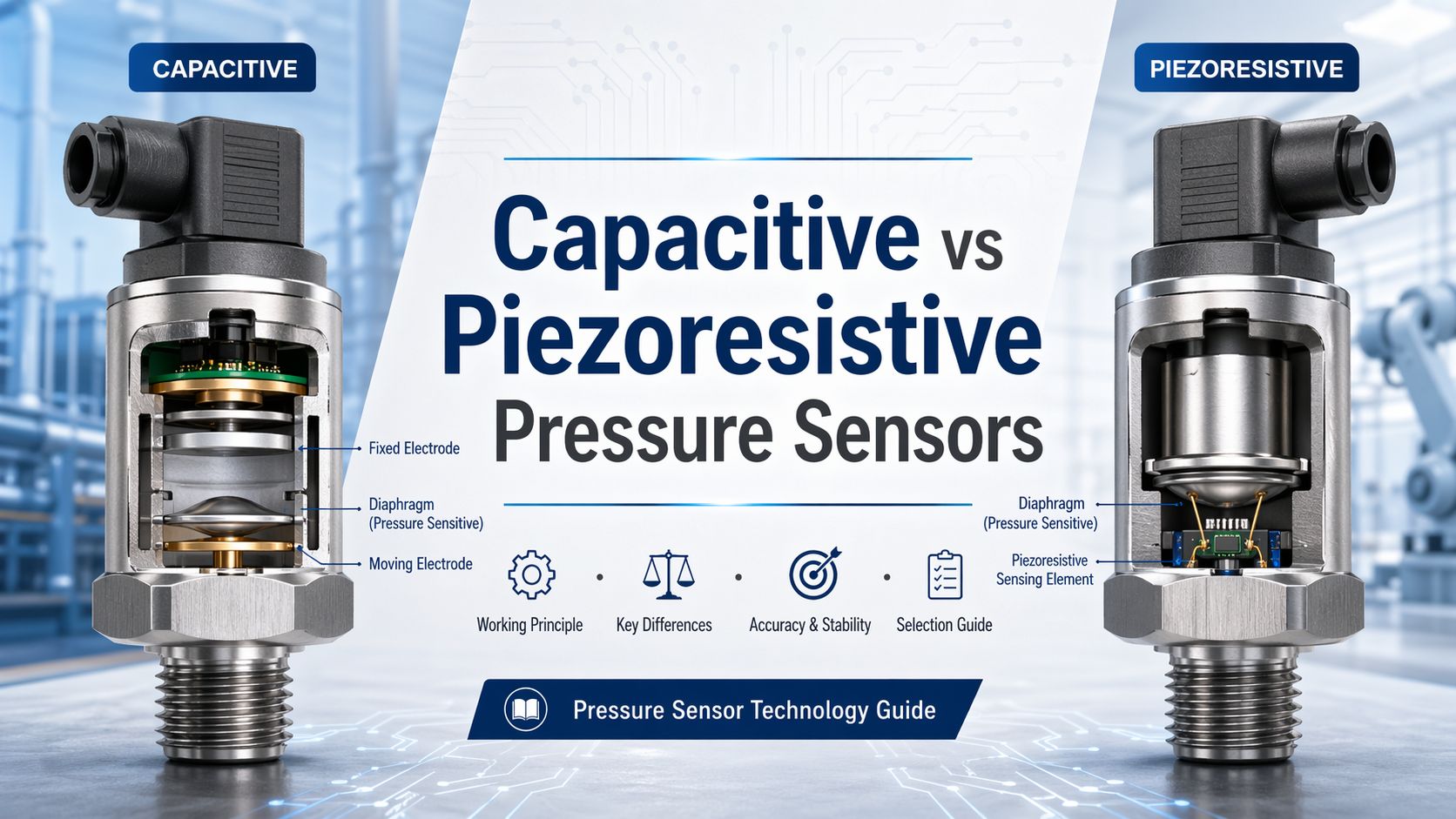
A piezoresistive sensor uses a diaphragm that flexes under pressure. Strain on the diaphragm changes the resistance of piezoresistors, typically arranged as a four-resistor Wheatstone bridge on the sensor die (very common in automotive MEMS pressure transducers).

What you measure: bridge output voltage (often mV/V) proportional to pressure.

Capacitive pressure sensors

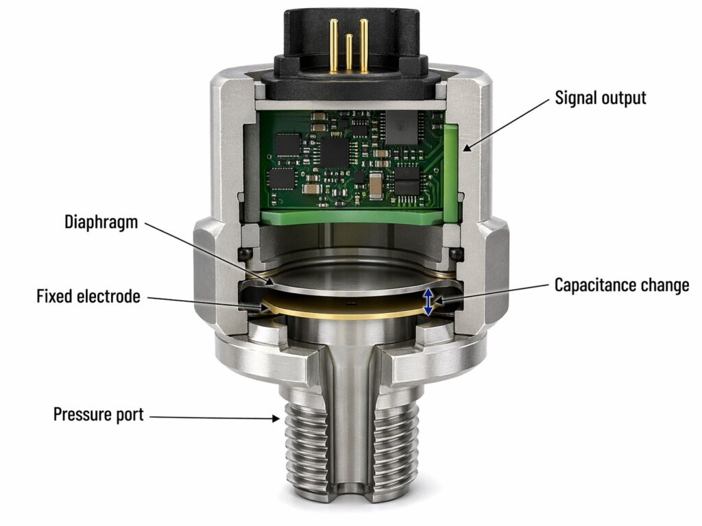
A capacitive sensor forms a capacitor where one plate is a pressure-deflected diaphragm. Pressure changes the diaphragm position (gap), changing capacitance. That capacitance change is read out using an AC method (charge/discharge timing, oscillator frequency shift, etc.).

What you measure: capacitance (or a derived frequency/time signal) proportional to pressure.

2) Key performance differences (what matters in real designs)

A) Power consumption

  • Capacitive: typically lower power at the sensing element because no DC current needs to flow through the capacitor; current mainly flows during measurement cycles, and passive/readout-powered schemes are possible in some designs.
  • Piezoresistive: requires excitation power for the bridge; scaling down resistance can increase power demand, which hurts battery systems.

Rule of thumb: if you’re building battery/remote/IoT pressure nodes, capacitive often has an advantage in power budget.


B) Temperature behavior (offset/span drift)

  • Piezoresistive outputs are temperature dependent and usually require compensation (offset + span drift are classic issues).
  • Capacitive sensors are often described as having low temperature sensitivity and good repeatability (in many implementations), though electronics and packaging still matter.

Practical implication: if your application sees large temperature cycles (e.g., under-hood, outdoor, tire/road thermal cycling), temperature compensation strategy becomes a major differentiator—often more important than the sensing principle itself.


C) Linearity, hysteresis, repeatability

  • Piezoresistive: generally provides linear output with pressure and simple signal conditioning.
  • Capacitive: can show nonlinearity because capacitance is inversely proportional to the electrode gap; “touch mode” designs can improve linearity and over-range robustness, but may introduce hysteresis tradeoffs.

If you need very low hysteresis at low pressures, capacitive is often attractive (many designs report low hysteresis + good repeatability), but confirm this in the actual datasheet and under your mounting/environment conditions.


D) EMI, parasitics, cabling/layout sensitivity

This is where capacitive designs often demand more system-level discipline:

  • Capacitive: performance can be strongly affected by parasitic capacitance, grounding, cable length, and nearby conductors; active shielding/guarding is a common mitigation strategy in capacitive sensing front ends.
  • Piezoresistive: bridge sensors are generally more straightforward to route and read (though they still require good analog practices for offset/drift/noise).

Design takeaway: if your electronics are far from the sensing element, capacitive can become challenging unless you use a well-designed CDC/AFE and shielding approach.


E) Overpressure tolerance and harsh events

  • Capacitive sensors are often described as tolerant of short-term overpressure, and touch-mode structures can provide large over-range capability.
  • Piezoresistive sensors are widely considered robust with good resistance to shock/vibration and dynamic pressure changes (implementation-dependent).

Reality check: overload performance is heavily driven by mechanical design (diaphragm thickness, stops, isolation diaphragm/oil fill, porting), not only the sensing principle.

3) Typical pressure ranges and “sweet spots”

Published ranges vary widely, but a representative guide summarizes:

  • Piezoresistive: commonly used from low pressures up to very high pressures (e.g., up to ~20,000 psi / 150 MPa noted in one engineering guide).
  • Capacitive: can cover vacuum/low pressure to high pressure (e.g., down to a few hundred Pa and up to ~10,000 psi / 70 MPa in the same guide), with strong performance in lower-pressure applications.

Practical “sweet spot” summary

  • Very low differential pressure (Pa to low kPa): capacitive often shines (sensitivity).
  • Very high pressure / rugged industrial transmitters: piezoresistive is extremely common and cost-effective.

4) Application-based decision guide

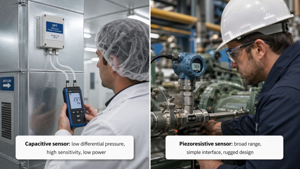
HVAC duct static pressure / filter monitoring (low DP)

  • Often favors capacitive for sensitivity at very low ΔP, but only if you control moisture/EMI/parasitics well.
  • Piezoresistive DP sensors are also common; choose based on total error band across temperature and installation constraints.

Hydraulics, compressors, general industrial gauge pressure

  • Piezoresistive is typically the default choice: mature, durable, simple readout, wide range availability.

Battery-powered / wearable / implanted / passive-readout concepts

  • Capacitive can be attractive because it can be inherently low-power and can be integrated into resonant/AC readout schemes.

Environments with challenging EMC or long cabling

  • If you can’t guarantee short connections + shielding, piezoresistive often reduces risk (simpler analog chain).

5) Selection checklist (what to put in your RFQ/datasheet)

Regardless of principle, specify these clearly:

  1. Pressure type: absolute / gauge / differential
  2. Range & overload: working range + proof/burst requirements
  3. Accuracy definition: %FS vs %reading, include temp range and “total error band” approach
  4. Temperature profile: operating + compensated range; ask how offset/span drift is handled
  5. Environment: humidity/condensation, vibration, EMI, ingress rating
  6. Mechanical: port/thread, media isolation needs, mounting stress sensitivity
  7. Electronics/interface: mV/V bridge vs voltage/current vs digital; for capacitive, ask about CDC/AFE and shielding guidance

6) Common pitfalls (and how to avoid them)

Pitfall 1: Assuming capacitive is “always more accurate”

Capacitive can offer excellent performance, but parasitic capacitance, layout, and shielding can dominate real accuracy if not handled correctly.

Pitfall 2: Underestimating temperature drift in piezoresistive designs

Temperature influence often appears as offset and span changes, so compensation is part of the product, not an optional extra.

Pitfall 3: Comparing only the sensing element, ignoring packaging

Isolation diaphragm + fill fluid + mechanical stops can decide hysteresis, overload survivability, and long-term drift more than the core principle.

FAQs

Which is better for low differential pressure: capacitive or piezoresistive?

Often capacitive, because it can be very sensitive at low pressures and shows good repeatability in many designs—but only if parasitics/EMI are controlled with proper front-end design and shielding.

Which technology is easier to interface?

Piezoresistive bridge sensors usually have simpler readout (bridge + amplifier/ADC). Capacitive sensors often need a dedicated capacitive front end (CDC/oscillator timing) and careful layout.

Which one handles temperature swings better?

Many guides describe capacitive sensors as having low temperature sensitivity, while piezoresistive sensors need stronger compensation due to temperature-dependent output characteristics.

Can both be used for absolute, gauge, and differential pressure?

Yes—both piezoresistive and capacitive pressure sensors can be implemented for absolute, gauge, relative, or differential measurements.

Leave a Reply

Your email address will not be published. Required fields are marked *