These three sensor principles are all used to measure pressure—but they behave very differently in the real world. The fastest way to choose correctly is to answer one question first:
Do you need accurate “true static pressure” (DC), or do you need fast dynamic pressure (AC)?
A recent technical review of pressure sensing principles highlights that sensor selection is fundamentally about matching the measurement principle to the industrial use case (static vs dynamic, environment, conditioning, packaging).
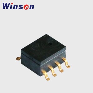
A piezoresistive pressure sensor uses a diaphragm that deflects under pressure. Stress in the diaphragm changes the resistance of piezoresistors (often diffused into silicon) arranged as a Wheatstone bridge; the bridge outputs a small voltage (mV/V) proportional to pressure. This “silicon diaphragm + bridge” concept is a core feature of MEMS piezoresistive pressure sensors.
Strengths
Measures static and dynamic pressure (good DC response)
Simple interface: bridge output → amplifier/ADC
Widely available across ranges (from low-pressure to high-pressure with proper diaphragm design and packaging)
Typical weaknesses
Temperature effects and drift need compensation (offset/span changes)
Kistler’s overview also describes practical implementations where pressure is coupled through a membrane and silicone oil to the silicon chip, then compensated/amplified—illustrating how “packaging + electronics” matter as much as the sensing element.
Best-fit applications
General industrial pressure transmitters (gauge/absolute)
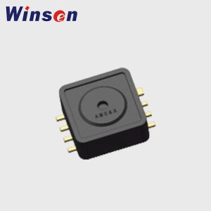
A capacitive pressure sensor forms a capacitor (electrodes + dielectric gap). Pressure deflects the diaphragm, changing the gap and therefore capacitance. This is the basic definition used in engineering guides.
Common MEMS architectures include:
Gap-varying (non-touch) mode: capacitance increases as the gap decreases
Touch mode: diaphragm makes controlled contact with an insulating layer at higher pressure, changing sensitivity/linearity behavior (design-dependent). Touch-mode capacitive designs are widely studied in MEMS literature.
Strengths
Excellent sensitivity for low pressures and small deflections
Potentially low power at the sensing element (no DC bridge current through resistors)
Good for differential pressure designs (two-chamber structures)
Typical weaknesses
More sensitive to parasitic capacitance, EMI, cable layout, humidity/contamination
Requires careful analog front-end design (capacitance-to-digital conversion, shielding/guarding)
Can be nonlinear over large deflection ranges unless the design uses differential capacitors or touch-mode strategies
MEMS pressure for portable/low-power devices (when designed with robust packaging and electronics)
3) Piezoelectric sensors (stress → electric charge)
Working principle
Piezoelectric materials generate electric charge when mechanically stressed. In pressure sensors, pressure changes create charge that is converted to voltage using a charge amplifier or suitable conditioning.
Strengths
Excellent dynamic response (fast transients, high bandwidth)
High stiffness and ruggedness are common in dynamic pressure designs
Key limitation (critical!)
Piezoelectric pressure sensors are typically not suited for true static pressure measurement (the signal decays over time for constant load and depends on conditioning). PCB’s technical note states piezoelectric pressure sensors measure dynamic pressure and are typically not suited for static pressure measurements.
Long-term drift/hysteresis expectations (especially for industrial transmitters)
FAQs
Can piezoelectric pressure sensors measure static pressure?
They are typically not suited for static pressure measurements; they excel at dynamic pressure.
Which is better for HVAC filter monitoring: piezoresistive or capacitive?
For very low differential pressures, capacitive sensors often shine due to sensitivity, but piezoresistive DP sensors are also common—final choice depends on noise/EMI, humidity, packaging, and cost targets.
Which technology is most common in MEMS pressure sensors?
Both piezoresistive (bridge in silicon diaphragm) and capacitive (diaphragm capacitor, including touch-mode designs) are widely used in MEMS.
Why do two sensors with the same principle perform differently?
Because packaging, media isolation, compensation, and signal conditioning dominate real-world accuracy, drift, and reliability.