
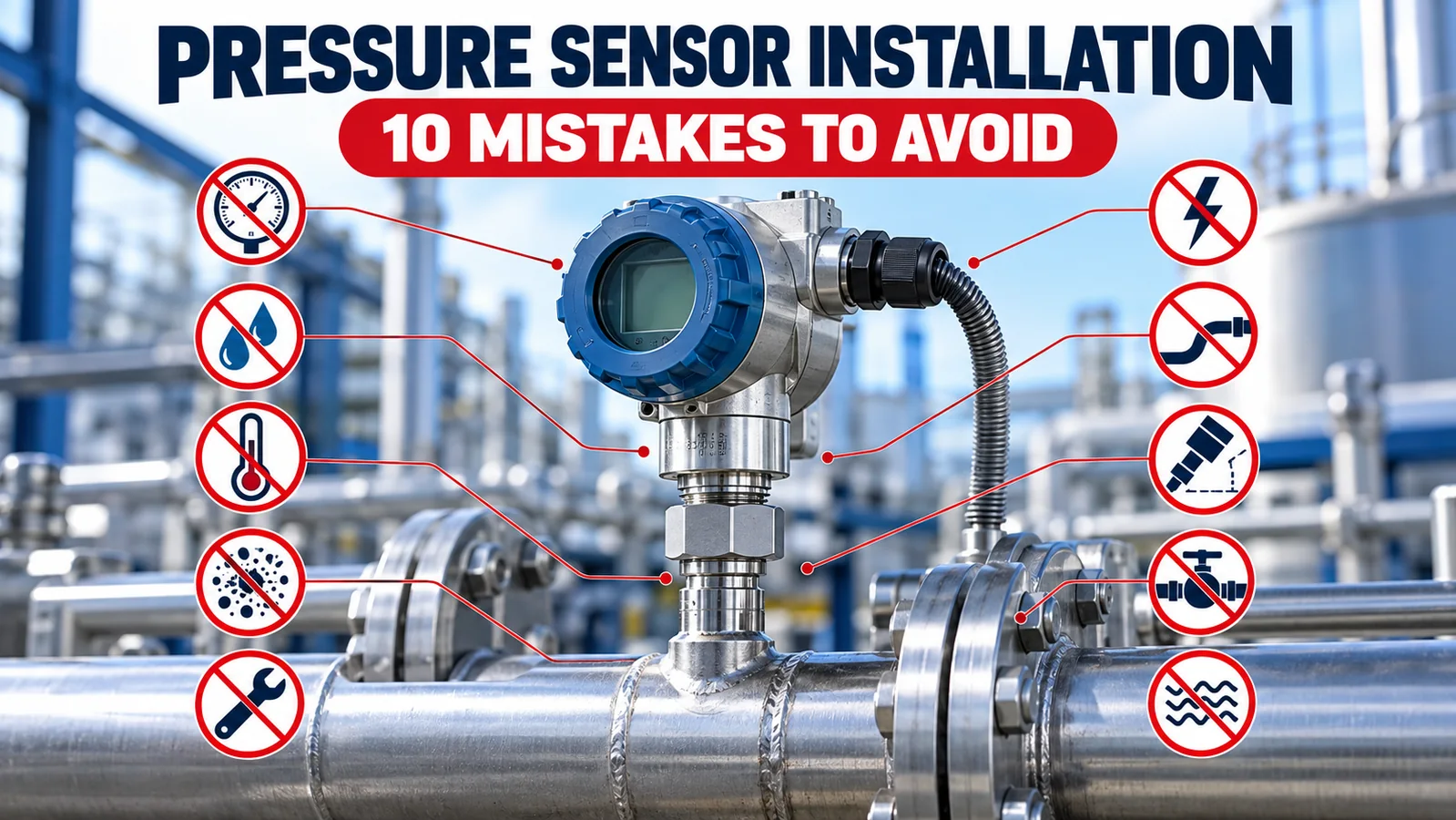
The most common pressure sensor installation mistakes are not exotic sensor failures. They are mismatched threads, incorrect seals, uncontrolled tightening, blocked pressure passages, trapped gas or liquid, poor tubing routes, vibration, wrong wiring, obstructed reference vents and skipped commissioning checks.
A correct installation begins before a wrench touches the process. Confirm the exact ordered sensor, pressure reference, range, overpressure limit, process connection, wetted materials, seal, output, power, temperature limits and environmental protection. Then install and commission the whole pressure path—from process tap to controller input—as one measurement system.
This guide organizes ten mistakes in the order an installer or OEM team can prevent them.
Mistake 1: Installing Before Confirming the Process Envelope
A sensor can fit mechanically and still be wrong for the application. Before installation, record:
- normal, minimum and maximum process pressure;
- startup, shutdown, surge and blocked-line pressure;
- gauge, absolute, sealed-gauge or differential reference;
- medium and every wetted material;
- process and ambient temperature;
- required response and pulsation conditions;
- output, supply, controller input and cable distance;
- location humidity, washdown, dust, vibration and hazardous-area requirements.
The measurement range is not automatically the safe overpressure limit. A sensor selected for normal operation may be damaged by a pump start, valve closure or pressure test. Add an approved snubber, restrictor, siphon, remote seal or mechanical isolation only when the sensor and process design call for it; every added component also changes response, dead volume and maintenance needs.
The industrial pressure-sensor selection guide provides a fuller pre-purchase checklist. At installation, compare the received model code and label with that specification. Do not assume that two housings that look alike have the same pressure reference or electrical output.
Mistake 2: Mixing Thread Standards or Sealing Methods
A G1/4 connection and a 1/4 NPT connection are not interchangeable. A parallel G/BSPP thread normally uses a defined face, shoulder, gasket or O-ring sealing geometry. A tapered NPT thread seals along engaged thread flanks with an approved sealant and the correct mating port.
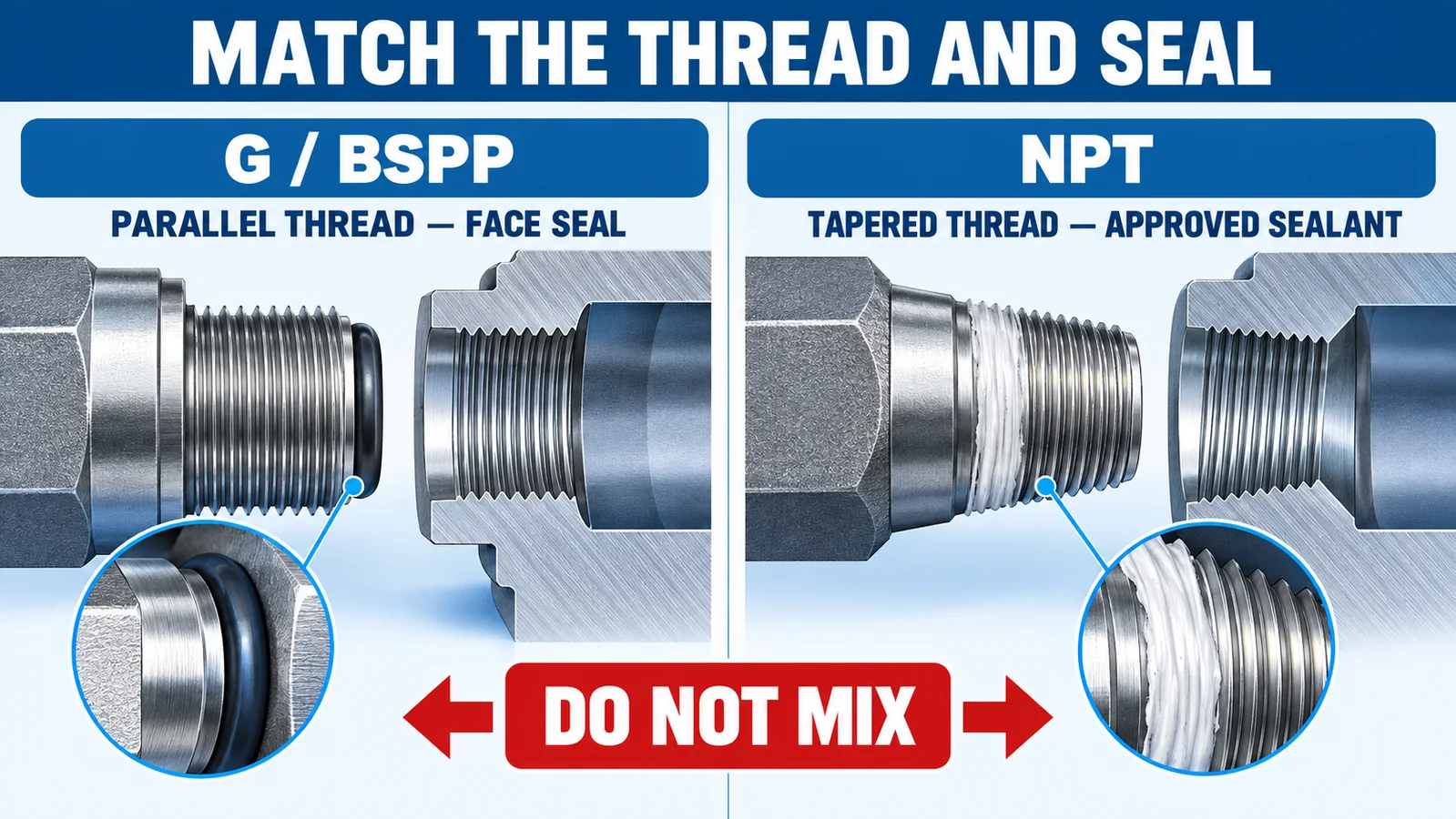
Installing a parallel male thread into a tapered female port can give partial engagement without a reliable pressure seal. Adding more tape does not convert one standard into another.
Match all parts of the joint
Check the complete connection:
| Item | What to verify |
|---|---|
| Thread designation | G/BSPP, NPT, metric or another stated standard |
| Male and female geometry | Diameter, pitch, taper/profile and engagement |
| Sealing location | Thread flank, face, shoulder, cone or O-ring groove |
| Seal material | Medium, temperature, pressure and regulatory compatibility |
| Port drawing | Depth, counterbore, sealing face and clearance |
| Installation instruction | Approved sealant, tightening method and reuse rules |
The NPT-versus-G pressure connection guide explains these geometries in depth. Use the exact sensor and fitting documentation; a generic thread chart cannot establish the seal design of a proprietary port.
Keep sealant out of the pressure passage
Excess tape or paste can shear off and enter a small pressure port. Apply only the approved product, amount and direction. Keep the first thread or specified area clear when the fitting instruction requires it. For a face-sealed parallel connection, wrapping the thread may interfere with seating and contaminate the process without improving the intended seal.
Mistake 3: Tightening the Housing Instead of the Spanner Flats
The electrical housing, cable gland and connector are not wrench surfaces. Twisting the housing can damage internal wires, change connector orientation, disturb seals or apply stress to the sensing assembly.
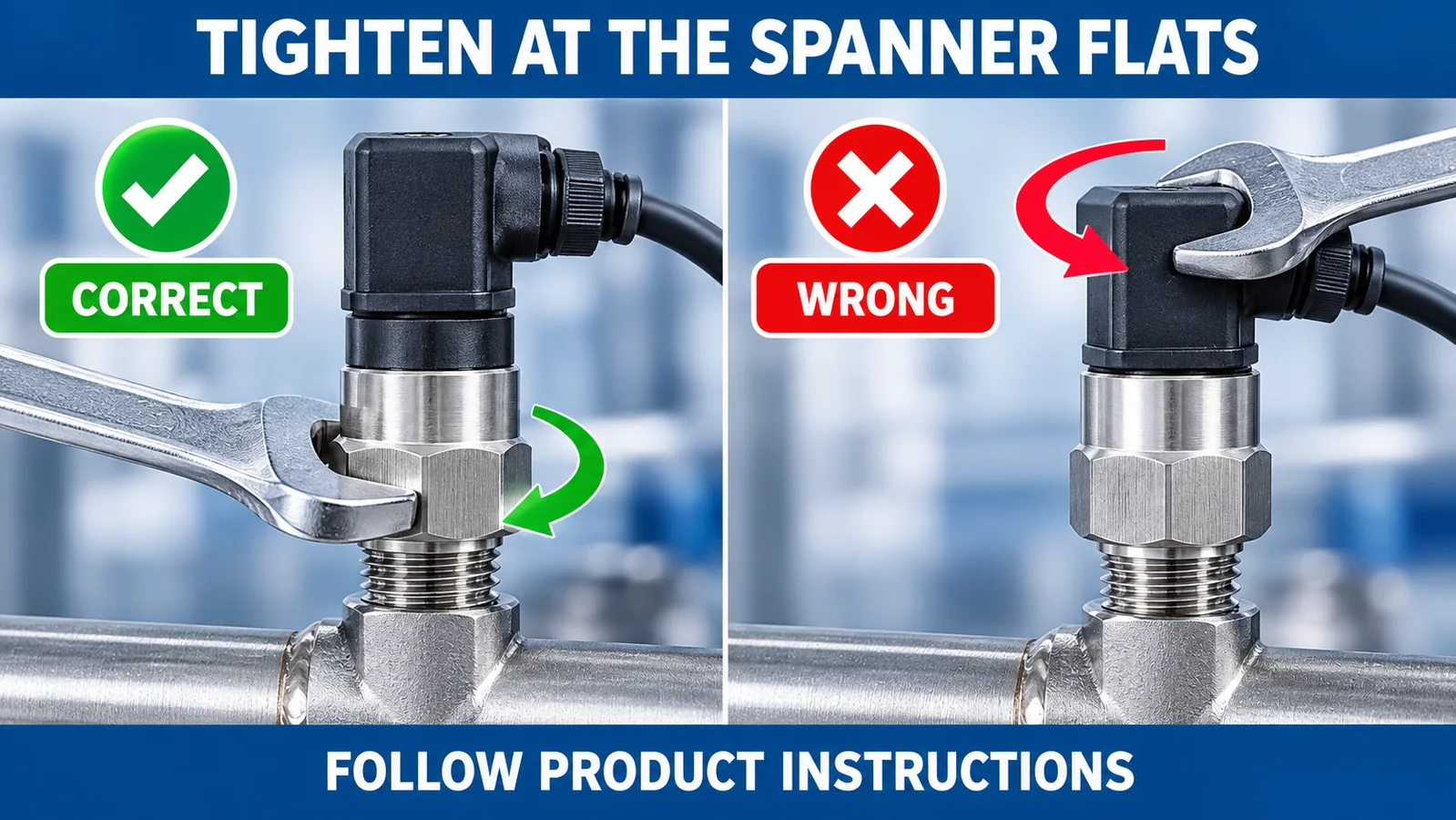
Start the connection by hand to avoid cross-threading. Then use the specified spanner flats and an appropriate wrench or torque wrench. The correct torque depends on the sensor connection, mating-port material, seal design, lubrication and manufacturer instruction. There is no safe universal torque for all pressure sensors.
More torque is not a repair method
If a joint leaks, first isolate and depressurize it safely. Find the actual leak point and inspect the thread, seal, sealing face, adapter and port. Stronger tightening can crush an O-ring, distort a gasket, strip a thread or overload a flush diaphragm. Replace a single-use or damaged seal rather than repeatedly tightening it.
Mistake 4: Blocking or Damaging the Pressure Port
Small passages and exposed diaphragms are vulnerable during storage and installation. Common errors include:
- removing the protective cap too early;
- leaving machining chips, burrs or old sealant in the port;
- pushing a wire or hard tool into the pressure opening;
- allowing tape or paste to cover the passage;
- touching or cleaning a diaphragm with an unapproved object;
- welding or flushing nearby without protecting the sensor.
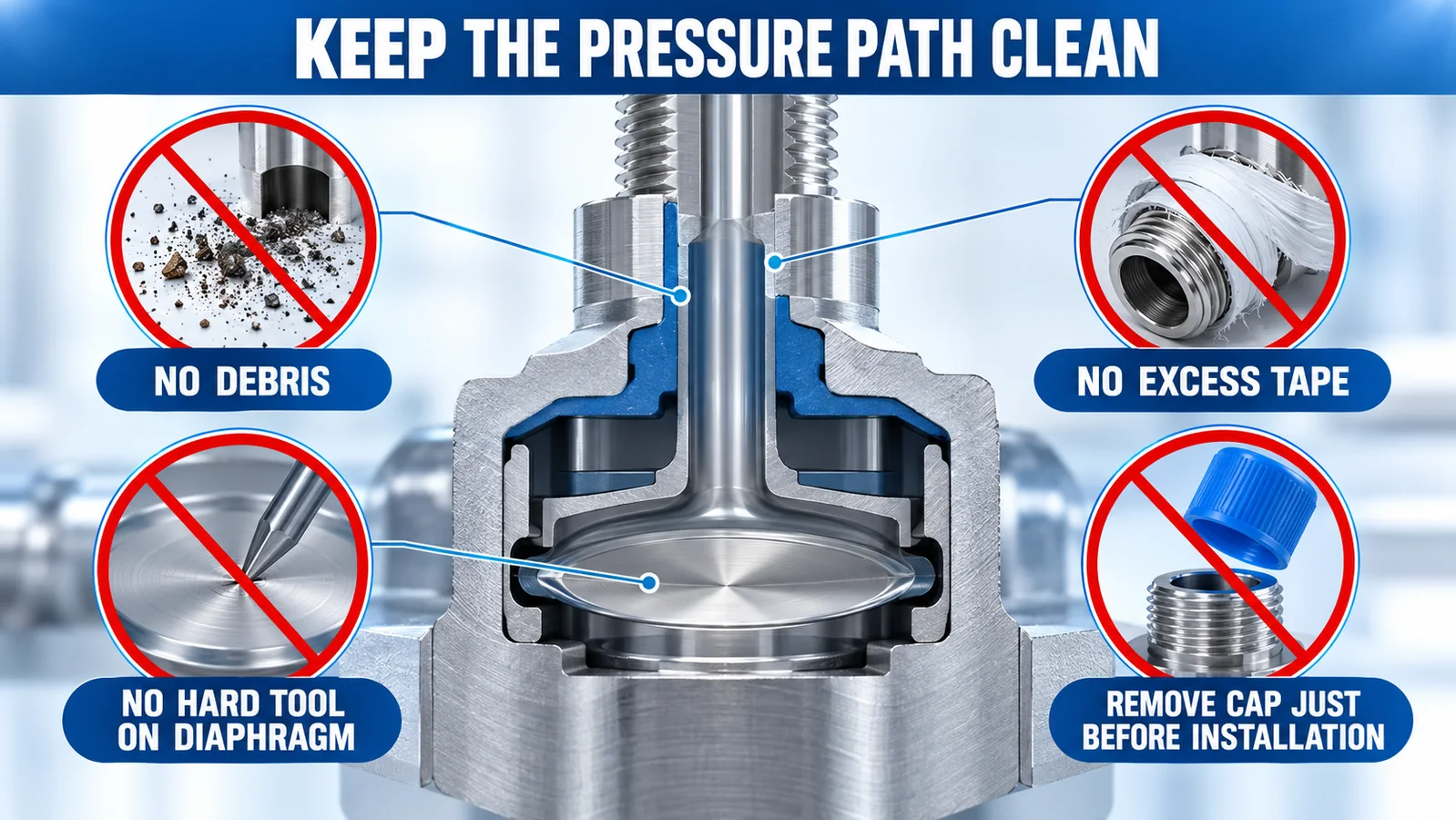
Keep the protective cap on until the installation area is clean and ready. Inspect the mating port and sealing face. Do not apply compressed air, solvents, ultrasonic cleaning or mechanical probes unless the product instructions explicitly permit them.
A blocked port can look like a failed sensor
A partially blocked passage may cause slow response, hysteresis-like behavior or a pressure reading that changes after a long delay. A completely blocked passage can trap an old pressure. Before replacing electronics, compare the sensor with a reference instrument and verify the process path under a safe maintenance procedure.
Mistake 5: Ignoring Orientation and Trapped Gas or Liquid
Orientation can affect venting, drainage, sediment collection, condensation and the position of an atmospheric reference vent. The correct arrangement depends on the medium, sensor structure and process connection; do not apply one orientation rule to every sensor.
In liquid service, a trapped gas pocket is compressible. It can delay pressure transmission and make dynamic response appear damped. In gas or steam-related service, trapped condensate can create a liquid head, freeze, corrode tubing or expose a sensor to an unintended temperature.
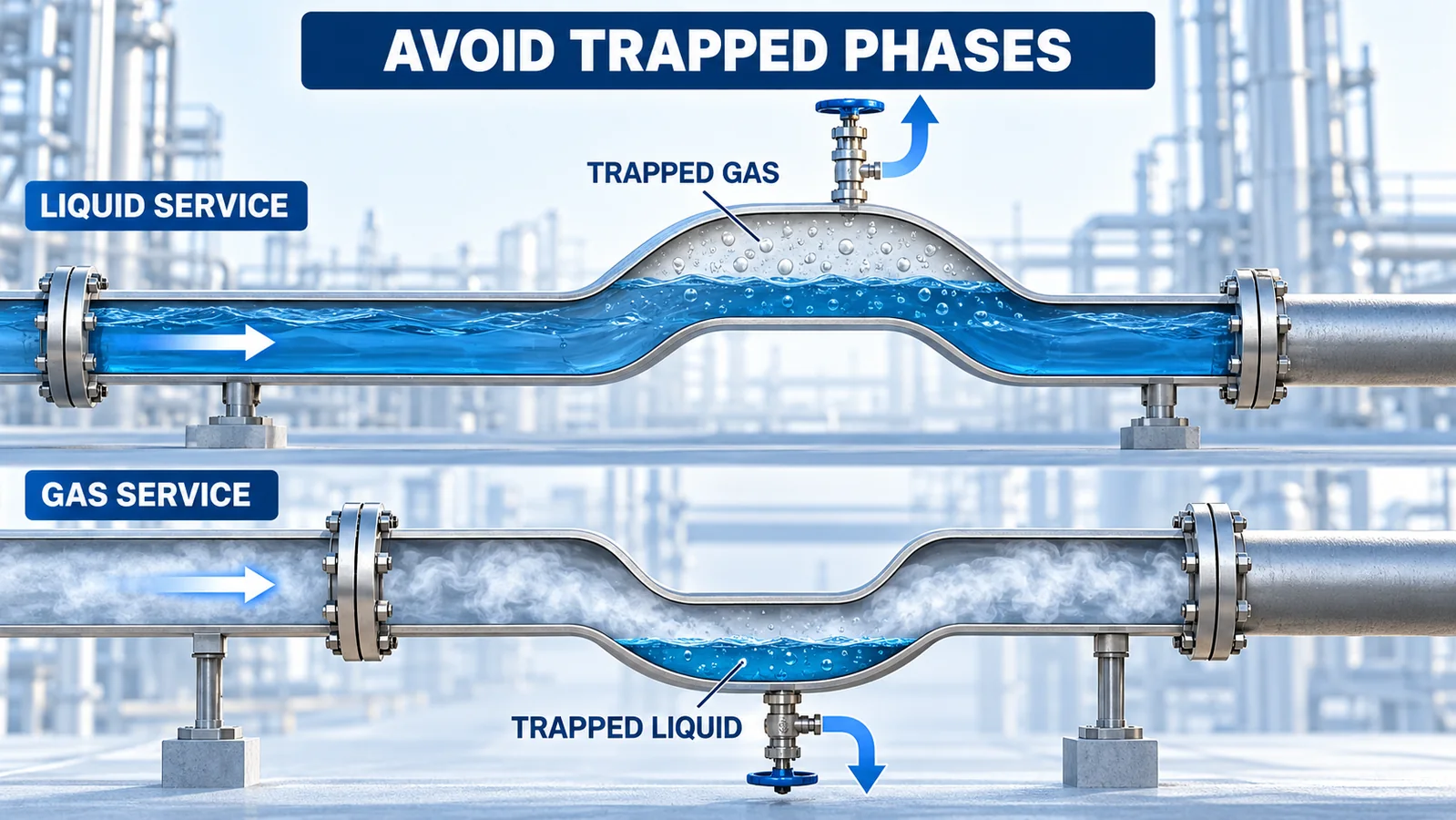
Design the takeoff and line so unwanted gas can be vented and unwanted liquid can be drained under the approved procedure. If the process contains solids, crystallizing media or viscous material, choose a connection and maintenance method that prevents accumulation. A flush diaphragm or remote seal may help in some services, but it changes the selection and installation requirements.
Mistake 6: Routing Impulse Lines and Tubing Poorly
The sensor measures the pressure delivered through its process path. A perfect transmitter cannot compensate for a leaking, kinked, blocked or wet tube.
For remote-mounted sensors and differential measurements:
- use tube and fittings rated for the pressure, temperature and medium;
- keep lines protected from impact and sharp bends;
- provide appropriate slope, drain or vent points;
- minimize unnecessary volume when response time matters;
- support tubing so it does not load the sensor port;
- label high and low sides at both ends;
- keep paired differential lines as thermally similar as practical;
- leak-test every joint by an approved method.
For air systems, condensation can collect at low points and create a false pressure head or block a low-range line. For liquid systems, elevation differences create hydrostatic head. Document the sensor elevation and any zero adjustment. A field “zero” that hides a permanently incorrect line arrangement makes later maintenance harder.
Mistake 7: Mounting in Excessive Heat, Vibration or Pulsation
Process temperature and ambient temperature are different limits. A transmitter body mounted beside a hot pipe, compressor head or uninsulated steam line may exceed its electronics limit even when the process connection survives. Conversely, a remote cooling element or impulse line can create condensation and response delay.
Vibration can loosen joints, fatigue wires and create mechanical stress. Pressure pulsation can repeatedly load the diaphragm and saturate a controller. Evaluate both the sensor’s published vibration/shock capability and the mechanical installation.
Separate the sensor from the disturbance when required
Options can include a supported bracket, flexible process connection approved for the service, snubber, pulsation damper, siphon or remote seal. Select these as engineered components—not improvised accessories—and validate their effect on response and cleanability.
In air-compressor systems, for example, discharge pulsation, heat and condensate can coexist. The air-compressor pressure-sensor guide discusses that application envelope.
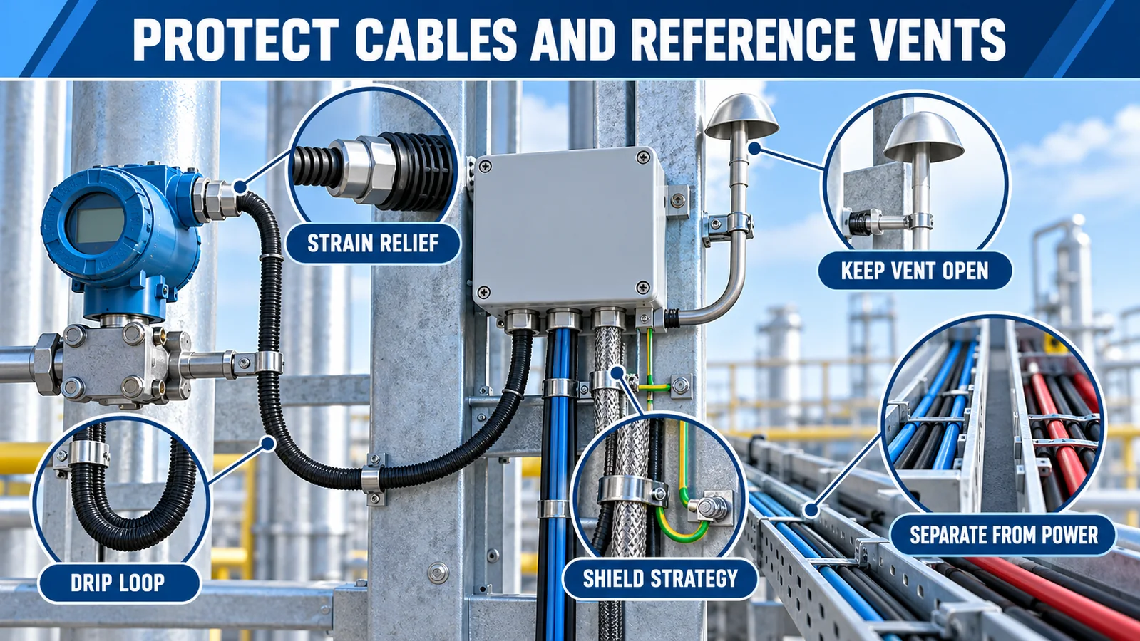
Mistake 8: Wiring by Color or Ignoring Grounding and Strain Relief
Wire color is not a universal signal definition. Confirm the exact model’s pinout for power, ground, analog output, current loop, digital bus and shield. Reversing a two-wire loop, applying supply to an output pin or using the wrong pull-up voltage can damage the device or create an apparently dead signal.
Before energizing:
- verify supply voltage and polarity at the installed connector;
- check controller input type and range;
- confirm cable shield termination strategy;
- separate low-level signal wiring from motors, contactors and variable-frequency-drive cables;
- provide strain relief so cable force does not reach the connector;
- seal unused cable entries with rated components;
- verify grounding and isolation requirements for the equipment.
A 4–20 mA input, voltage input and I²C interface are not substitutes for one another. Controller configuration must match the sensor’s ordered output.
Mistake 9: Blocking the Gauge Reference Vent or Inviting Condensation
A vented gauge sensor compares process pressure with local atmospheric pressure. Blocking or wetting that reference path can shift the reading. Some devices reference atmosphere through a housing vent; others use a vented cable or protected opening. Follow the exact product instruction.
Do not paint over a vent, bury it in sealant, place it where washdown accumulates or route a vented cable end into a wet junction box. Use drip loops, appropriate cable glands and an enclosure arrangement that allows drainage without defeating the required ingress protection.
IP rating is not an installation shortcut
An enclosure rating applies under specified test and assembly conditions. A loose gland, wrong cable diameter, damaged O-ring, open connector or blocked reference can invalidate the practical protection. Inspect all interfaces after installation.
For sealed-gauge or absolute devices, the reference construction is different, but moisture at the connector and cable entry can still cause failure. Confirm the pressure reference rather than assuming every gauge-labeled product vents the same way.
Mistake 10: Skipping Commissioning and Documentation
An installed device is not commissioned merely because the controller displays a number. Complete at least four verification layers:
- Mechanical: correct model, connection, seal, support and leak tightness.
- Pressure path: open valves, clear tubing, correct high/low routing, no trapped phase.
- Electrical: supply, polarity, signal type, shielding and controller scaling.
- Measurement: zero condition, reference comparison, functional pressure change and alarm/control response.

Compare against the same pressure point
Use a suitable calibrated reference connected to the same pressure point or approved test manifold. A disagreement between instruments at different elevations or across a flowing restriction may be a real pressure difference, not sensor error.
Record the model and serial/lot data, range, reference type, output, port, seal, torque procedure, cable ID, controller channel, scaling, zero method, test reference, as-left readings and date. This record prevents the next technician from “fixing” a correct configuration with undocumented changes.
A Pre-Start Installation Checklist
| Check | Pass condition |
|---|---|
| Model and range | Match approved datasheet and process specification |
| Pressure reference | Gauge, absolute, sealed gauge or differential is documented |
| Process connection | Sensor, adapter and port use matching standards |
| Seal | Correct geometry, material, condition and placement |
| Tightening | Hand-started; tightened at flats per instruction |
| Pressure path | Clean, open, supported and correctly vented/drained |
| Environment | Temperature, vibration, moisture and ingress controls addressed |
| Wiring | Pinout, power, output, shield and strain relief verified |
| Reference vent | Correctly located and unobstructed where applicable |
| Commissioning | Leak, zero, reference, scaling and function tests recorded |
What Do WPCK63 and WPCH01 Illustrate?
The official WPCK63 page lists a standard M20×1.5 pressure thread, a 316L stainless-steel diaphragm and 0.2–2.3 V or I²C output for the published configuration, with other outputs described as customizable. Its exact ordered configuration determines the supply, wiring, seal and mating port.
The official WPCH01 page describes a ceramic pressure transmitter with configurable electrical outputs and process connections. The WPCH01 manual lists G, NPT and metric connection options and multiple electrical terminations. That flexibility is precisely why installers must use the full order code and current variant drawing rather than a family name alone.
Neither example creates a universal installation rule. Confirm the current datasheet, ordered port, wiring and seal with Winsen before final equipment release.
Frequently Asked Questions
Can I use PTFE tape on every pressure sensor thread?
No. Tapered threads may use an approved thread sealant, while parallel threads often seal at a face or O-ring. Use the exact connection instruction and keep sealant out of the pressure passage.
How tight should a pressure sensor be?
Use the torque or installation method specified for the sensor, fitting, seal and mating material. There is no universal torque. Tighten at the spanner flats, not the housing.
Which direction should a pressure sensor face?
The correct orientation depends on the medium, process takeoff, vent/drain needs, sensor construction and environmental protection. Avoid arrangements that trap the wrong phase or expose a vent/cable entry to water.
Why does a liquid-pressure sensor respond slowly?
Possible causes include trapped gas, a restricted port, a long or compliant hose, a snubber, viscous media or digital filtering. Verify the pressure path before adjusting the controller.
Why does a gauge-pressure reading change after washdown?
A reference vent, connector or cable entry may be wet or blocked. Isolate the process safely, follow the product inspection procedure and correct the enclosure/vent routing rather than recalibrating a temporarily affected signal.
Must a new sensor be field calibrated?
Requirements depend on the application and quality plan. At minimum, commission the installed loop with zero, scaling, functional and reference checks. Safety- or quality-critical systems may require traceable multi-point calibration.
Install the Measurement System, Not Just the Sensor
Reliable pressure data depends on the process tap, thread, seal, mounting force, pressure path, environment, wiring, reference and controller configuration. Preventing the ten mistakes above is usually faster and less expensive than troubleshooting an unstable reading after startup.
For an OEM or equipment project, send Winsen the process medium, range, pressure reference, connection, temperature, output, enclosure and installation constraints. Contact the Winsen team to confirm a suitable current configuration and obtain the correct variant documentation before release.
